Memory map and variables ($00—00)

0600 - 1E00: video memory
1CF8 - 1DEF: unknown data structure (initialed from $C135)
2029: player_sector_number copy? (initialized to same as player_sector at $D37B)
202A: player_sector_number (initialized to 0 at $C08E)
2035: unknown (added to alien_count at $D38A)
2036: *player_sector (initialized at $C12C)
2039: unknown (initialized to 0 at $C04B)
2045: unknown skill-based variable (initialized at $C039)
2047: unknown skill-based variable (initialized at $C03B)
204F: player_score right digits
2050: player_score left digits
2051: unused variable? (initialized to 3 at $C133)
2055: unknown (initialised to 0 at $C085)
2065: unknown skill-based variable (initialized at $C080)
2067: frame count (initialized to C000 at C08A)
2081 - 2101: aliens on playfield (initialized from $D1CF)
2129 - 22E2: unknown data structure (initialized from $D11D)
2519 - 2618: galaxy map, 64 sectors of 4 bytes each
 - byte 0 = alien_count
 - byte 1 = station_health
 - byte 2 = ??? (initialized to a random number 0-255)
 - byte 3 = station_type
26FA: random number seed byte 1 (initialized to 1 at $C013)
26FB: random number seed byte 2 (initialized to 1 at $C013)
26FC: random number seed byte 3 (initialized to 1 at $C013)
26FD: random number seed byte 4 / last random number used (initialized to 1 at $C013) - this byte copied to the accumulator when random_number() is called
26FE: unknown (initialized to 1 at $C007)
26FF: unknown (initialized to 1 at $C00B)
2700: skill level (initialized to 8 at $C00A)
3FFF: initial stack pointer (initialized at $C021)

Draw score ($C131—C157)

The easiest way to understand what this block of code is doing is look at the state of memory before and after. The main difference is some new entries in the video RAM, from $1CF8 to $1DDF. Recalling our earlier trick from "Load glyph data ($D86C—D8C6)" (TODO: link) to peek at the video memory, we end up with a set of bytes looking like this:

1CF8:    11111111        11111111        11111111        11111111
1D18:  11      1111    11      1111    11      1111    11      1111
1D38:  11    11  11    11    11  11    11    11  11    11    11  11
1D58:  11    11  11    11    11  11    11    11  11    11    11  11
1D78:  11  11    11    11  11    11    11  11    11    11  11    11
1D98:  11  11    11    11  11    11    11  11    11    11  11    11
1DB8:  1111      11    1111      11    1111      11    1111      11
1DD8:    11111111        11111111        11111111        11111111

This looks exactly like the player's score, when set to zero. Knowing this, it becomes much easier to guess at what our variables are.

C131: 86 03        LDA #$03    A = 3
C133: 97 51        STA $51     Set $2051 = 3

...except this one. $2051 is likely another global variable but it does not seem to be read or changed during a game.

C135: 8E 1C F8     LDX #$1CF8  X = $1CF8 (video_address, video RAM)
C138: 10 8E 20 4F  LDY #$204F  Y = $204F (score_address)
C13C: BD D8 29     JSR $D829   Jump to $D829

We saw the score start at $1CF8, so X clearly indicates the video address into which data will be written. $204F indicates an area of memory which starts with zeroed data but which, when we run the game, reflects the player's score in real-time. We therefore need no hesitation in labelling these variables video_address and score_address.

In fact byte $204F contains the hundreds and thousands,while byte $2050 contains the tens and ones. Each digit uses four bits (officially, but not popularly, know as a nibble). For example, if the score is 1550, then the individual bits will look like this:

Bits:   0001 0101 0101 0000
Number:    1    5    5    0
D829: 34 30        PSHS ,Y,X   Push video_address, score_address to stack
D82B: 86 02        LDA #$02    A = 2
D82D: 34 02        PSHS ,A     Push A to stack (loop_count_outer)

We push these variables to the stack, including a simple 2 which I know will only be used for looping. I call it loop_count_outer because there will shortly be an inner loop too.

D82F: A6 A4        LDA ,Y      A = score_address->val
D831: 8D 10        BSR $D843

The accumulator is loaded with the byte containing the 2 right digits of the player score.

D843: 34 30        PSHS ,Y,X   Push video_address, score_address to stack again

X and Y, which still contain the video_address and score_address respectively, are pushed to the stack again only for convenience; we want to access these again soon, but if we wanted to do so without making copies, we would have to navigate up the stack beyond loop_count_outer. Fiddling with the stack like that could be considered bad form, as it does make it easier to introduce subtle bugs.

We can call these copies video_address2 and score_address2.

D845: 44           LSRA        A >> 1
D846: 44           LSRA        A >> 1
D847: 44           LSRA        A >> 1
D848: 44           LSRA        A >> 1

We know that A contains a byte of the player score, with each of the two nibbles accounting for a digit each. Right-shifting A four times effectively isolates the high nibble digit, by moving it into the low nibble position and implicitly zeroing the high nibble. The entire byte in A now represents that one digit instead of two.

We then call - with needing to actually call it, as it happens to start from the next instruction - the function draw_digit(A), with the first digit that we want to draw.

# draw_digit(A)
D849: C6 10        LDB #$10    B = 16
D84B: 3D           MUL         digit * B
D84C: C3 D8 D7     ADDD #$D8D7 D = D + $D8D7 (ROM address)
D84F: 1F 02        TFR D,Y     Y = D
D851: AE E4        LDX ,S      X = video_address2

We start by finding where the glyph data for this digit exists on the cartridge ROM, by calculating an offset from $D8D7. From this we can extrapolate exactly where each number's data is stored. As it turns out they are simply store 16 bytes apart.

number Glyph in ROM
0 $D8D7
1 $D8E7
2 $D8F7
3 $D907
4 $D917
5 $D927
6 $D937
7 $D947
8 $D957
9 $D967
D853: 86 08        LDA #$08    A = 8
D855: 34 02        PSHS ,A     Push A to stack (loop_count_inner)
D857: EC A1        LDD ,Y++    D = Y, Y = Y + 1
D859: ED 84        STD ,X      X->val = D
D85B: 30 88 20     LEAX +$20,X X = X + 32
D85E: 6A E4        DEC ,S      loop_count_inner = loop_count_inner - 1
D860: 26 F5        BNE $D857   Loop until loop_count_inner = 0 (8 loops)

This is a simple function; re-written naively in C it would look more like this:

for (int i = 0; i < 8; i++)
{
    memory[X] = memory[Y];
    memory[X+1] = memory[Y+1];
    X += 32;
    Y += 1;
}

This small loop copies the data from cartridge ROM into video memory. Reading the ROM data is easy, as we just loop 8 times, reading 2 bytes each time. When writing it, we separate every 2 bytes with a 32-byte gap; as a complete horizontal line across the screen uses 32 bytes, this displays as 2 bytes per line.

In any case it's clear that we're populating a collection of 8 (still unknown) data structures that are 32 bytes wide.

D862: 32 61        LEAS +$01,S   Clean-up loop_count_inner
D864: 35 B0        PULS ,X,Y,PC  Clean-up video_address2 & score_address2, return to caller

We clean up all the stack variables, simultaneously using the trick of pulling the PC off the stack to simulate an RTS, and continue where we left off.

D833: 30 02        LEAX +$02,X X = X + 2 (video_address + 2)
D835: A6 A0        LDA ,Y+     A = Y->val, Y = Y + 1
D837: 8D 2D        BSR $D866

We've now popped the stack back to the point where X holds the initial video_address of $1CF8, and Y holds the initial score_address of $204F. We offset the video address by 2 bytes - which positions us 8 pixels to the right, at the insertion position for the next digit. The score address will actually remain as $204F, though Y is then incremented. This means that the next time it's accessed it will be pointing to $2050, which contains the two left-most digits of the score.

D866: 34 30        PSHS ,Y,X   Push video_address2 & score_address2 to stack
D868: 84 0F        ANDA #$0F   A = A & 00001111
D86A: 20 DD        BRA $D849   Call draw_number(A) on second digit

We call the draw function again, but this time we isolate the second digit. This is more simply done; recall that to isolate the high nibble we needed 4 right-shifts, but to isolate the low nibble we can simply remove the high nibble. This can be done with a simple AND mask.

A note on unorthodox branching

Note that we use a BRA here instead of a JSR, so the address of the current execution point is not placed on the stack. This means that when copy_rom_to_ram1() finishes and calls RTS (or uses PULS ,PC simulates it), we'll be returning to wherever we last used a BSR or JSR. In this case that will be at $D839. This execution flow is not something that can usually be achieved in a higher-level language, though it's really the same as:

JSR $B849
RTS

This form makes the execution flow explicit, at the cost of one extra byte and one extra instruction.

D839: 30 02        LEAX +$02,X  X = X + 2
D83B: 6A E4        DEC ,S       loop_count_outer = loop_count_outer - 1
D83D: 26 F0        BNE $D82F    Loop until loop_count_outer = 0 (2 loops)

Having now drawn two digits, the entire code from $D82F is repeated, but by now

  • score_address will be 1 byte higher at $2050 instead of $204F, and
  • video_address will be 4 bytes higher at $1CFC instead of $1CF8.

This will draw the remaining two digits of the player's score onto the screen.

D83F: 32 61        LEAS +$01,S  Clean-up loop_count_outer
D841: 35 B0        PULS ,X,Y,PC Clean-up video_address, score_address and return to caller

Clean-up, as usual, before continuing. Here is the fruit of our labours:

Player score 0000

Unknown ($D11D—D17B)

This one was hard to work out, so I'll reveal straight out what's happening: TODO: diagram, 8 bytes wide, 32 bytes high from 0x2129.

  • column 1 & 2 - from $2129 - set to all 0s
  • column 3 - from $212B - fill with 8 rows each of $5B, $68, $70, and $78.
  • column 4 - from $212C - random numbers between 0 and 255, where no two numbers are closer than 3 to each other.
  • column 5 & 6 - from $212D - fill with 8 rows each of $DCC6, $DCCC, $DCD2 and $DCD8. These appear to be ROM addresses
  • column 7 & 8 - from $212F - fill with 8 rows each of $3C78, $30A0, $28C0 and $22E2.

Set column 1 & 2

D11D: 8E 21 29     LDX #$2129   X = $2129
D120: CC 00 00     LDD #$0000   A = 0, B = 0
D123: ED 02        STD +$02,X   Set (X+2)->value = 0
D125: 30 08        LEAX +$08,X  X = X + 8
D127: 8C 22 29     CMPX #$2229  Check if X has reached $2229
D12A: 26 F7        BNE $D123    Loop to $D123 if not

Starting from $212B and until $2229, we loop over 8 byte chunks at a time, setting 2 of those bytes to 0 each time. TODO: grid showing all 256 bytes and highlighting which of those have been changed.

In simplified C, this would look like this:

for (int i = 0x2129; i < 0x2229; i += 8)
{
    memory[i] = 0;
    memory[i+1] = 0;
}

Set column 4

This is by far the most complicated logic to follow. We want to populate this column with a set of random numbers, but we want some degree of even distribution amongst these numbers. Specifically, no two numbers are to be within 3 of each other. For example, if one of our random numbers if 6, then we cannot for any of the other values choose the values 3, 4, 5, 6, 7, 8 or 9.

D12C: 8E 21 2C     LDX #$212C   insert_address = $212C
D12F: BD DB 1B     JSR $DB1B    candidate_random = random_number()
D132: 34 12        PSHS ,X,A    Push insert_address and candidate_random to the stack

We set our pointer X to the first row of column 4 ($212C), and generate a random number. By pushing these immediately on to the stack we indicate that we're about to re-use A and X for other purposes, but that we need these values later. Therefore we know that these values are variables, and we accordingly name them insert_address and candidate_random.

D134: 8E 21 2C     LDX #$212C   X = $212C
D137: A6 84        LDA ,X       A = X->val

We immediately reset the value of X to $212C. It's true that we already set it to $212C only three lines ago, but we'll be looping back later when it's a different value. We then load the value from that memory location into the accumulator.

D139: A0 E4        SUBA ,S      A = A - candidate_random

We now compare the candidate_random number - which is stored at the current stack position - with the current row of column 4.

D13B: 2A 01        BPL $D13E    Skip next line if the result is >= 0
D13D: 40           NEGA         A = -A
D13E: 81 03        CMPA #$03    Check A - 3
D140: 23 14        BLS $D156    If A <= 3 branch to on_failed_candidate()

Let's look ahead to $D13E first. Here we compare the result of our subtraction to 3. If the result is less than 3, then the candidate_random is too close to an existing value in the column, and we branch to on_candidate_failed(), which we will study shortly.

However, that comparison alone really only checks that the candidate_random is at least 3 less than the value in memory; in other words it checks this:

candidate_random <= X + 3

TODO: is this actually checking X - 3?

but we need to check if the candidate_random value is both 3 higher or 3 lower i.e.

X - 3 <= candidate_random <= X + 3

That's what $D13B and $D13D are for. By changing any negative value to a positive value we can then compare to a positive 3 and catch both cases.

BGE vs BPL

Why don't we use BGE here instead? They look pretty similar; both compare whether one number is greater than another. But as it turns out, BPL is great for comparing unsigned numbers while BGE is better for signed numbers. The key difference is that BGE considers not only the negative flag but also the overflow flag, which is set when the calculation causes an overflow or underflow of the byte boundaries at +128 or -127. The following table shows some calculations where this does or doesn't make a difference.

calculation mathematical result CPU result overflow negative BPL BGE
47 - 115 -68 -68 0 1 false false
47 - 21 26 26 0 0 true true
-90 - 40 -130 126 1 0 true false
126 - (-127) 253 -3 1 1 false true

When you study the table you can see why BGE is recommended for normal arithmetic; it correctly indicates whether the actual mathematical result of the calculation was positive or negative. But BPL ignores any overflow or underflow, and only looks at the final result on the CPU; as we'll see shortly, that is preferred in this case.

The sign reversal that occurs for negatives if A is negative - in effective the same as A = abs(A) - is clever because it makes the subsequent CMPA and BLS act like a check on whether A is within the range -3 to +3. In other words, in practice the branch occurs when -3 <= A <= 3.

The decision to compare A to the proposed byte using BPL rather than BGE makes it clear that we are comparing how close, in unsigned terms, the two bytes are. If A is $7E and the proposed byte is $81, this operation would not branch:

D139: A0 E4        SUBA ,S      A = $7E - $81
D13B: 2A 01        BGE $D13E    result = $FE (254 unsigned, -2 signed)
                                overflow = 1, negative = 1
                                does branch
D13D: 40           NEGA         (skipped!)
D13E: 81 03        CMPA #$03    Check A - 3, does not branch

But $7E and $81 are actually very close in quality. On a number line they are in sequence: 7E...7F...80...81. Using BPL will reflect this:

D139: A0 E4        SUBA ,S      A = $7E - $81
D13B: 2A 01        BPL $D13E    result = $FE (-2 signed)
                                overflow = 1, negative = 1
                                does not branch
D13D: 40           NEGA         A = 2
D13E: 81 03        CMPA #$03    Check A - 3, does branch

If they are 3 or less apart, we consider the proposed byte a failure and restart the loop with a new proposed byte:

D156: BD DB 1B     JSR $DB1B    Call random_number()
D159: A7 E4        STA ,S       Replace old random byte on stack with new random byte
D15B: 20 D7        BRA $D134    Go back to before start of loop

Note that while the "normal" loop goes back to $D137, this actually jumps back to one instruction before that, which includes the initialization of X to $212C.

D142: 30 08        LEAX +$08,X  X = X + 8
D144: 8C 22 2C     CMPX #$222C  Check if X has reached $222C
D147: 26 EE        BNE $D137    Branch to $D137 if not

The above code is executed when the proposed byte is not within close proximity to the tested byte. We then increment X to move on to the next byte to test, until we have tested all 32 bytes in the range.

D149: 35 12        PULS ,A,X    Pop random byte 1 and X off the stack
D14B: A7 84        STA ,X       X->val = random byte
D14D: 30 08        LEAX +$08,X  X = X + 8
D14F: 8C 22 2C     CMPX #$222C  
D152: 26 DB        BNE $D12F    Loop to $D12F until X = $222C
D154: 20 07        BRA $D15D    Skip past reset_loop() function

We reach this point once we have determined, by testing against all 32 bytes in the column, that the proposed byte is valid. The byte then gets stored at the next position in the column and we loop the whole thing again until all 32 places have been filled.

Set column 3

D15D: 8E 21 2B     LDX #$212B   X = $212B
D160: 86 5D        LDA #$5D     A = $5D
D162: 8D 0E        BSR $D172    copy_8x1bytechunks_8byteoffsets_fromA()
D164: 86 68        LDA #$68     A = $68
D166: 8D 0A        BSR $D172    copy_8x1bytechunks_8byteoffsets_fromA()
D168: 86 70        LDA #$70     A = $70
D16A: 8D 06        BSR $D172    copy_8x1bytechunks_8byteoffsets_fromA()
D16C: 86 78        LDA #$78     A = $78
D16E: 8D 02        BSR $D172    copy_8x1bytechunks_8byteoffsets_fromA()
D170: 20 0A        BRA $D17C

The above code populates the data in column 3, from $212B down to $2223. The helper function, is shown below.

# copy_8x1bytechunks_8byteoffsets_fromA()
D172: C6 08        LDB #$08
D174: A7 84        STA ,X
D176: 30 08        LEAX +$08,X
D178: 5A           DECB
D179: 26 F9        BNE $D174
D17B: 39           RTS

The helper function performs a simple loop 8 times, setting one byte each time, somewhat like this:

for (int i = 0x212B; i < 0x2223; i += 8)
{
    memory[i] = A
}

Set column 5 & 6

D17C: 8E 21 2D     LDX #$212D   X = $212D
D17F: 10 8E DC C6  LDY #$DCC6   Y = $DCC6
D183: 8D 14        BSR $D199    copy_8x2bytechunks_8byteoffsets_fromY()
D185: 10 8E DC CC  LDY #$DCCC   Y = $DCCC
D189: 8D 0E        BSR $D199    copy_8x2bytechunks_8byteoffsets_fromY()
D18B: 10 8E DC D2  LDY #$DCD2   Y = $DCD2   
D18F: 8D 08        BSR $D199    copy_8x2bytechunks_8byteoffsets_fromY()
D191: 10 8E DC D8  LDY #$DCD8   Y = $DCD8
D195: 8D 02        BSR $D199    copy_8x2bytechunks_8byteoffsets_fromY()
D197: 20 0B        BRA $D1A4

TODO: Are we storing actual addresses here rather than actual values? - remains to be seen how we read them.

The above code populates the data in column 5 and 6, from $212D down to $2225. The helper function, is shown below.

# copy_8x2bytechunks_8byteoffsets()
D199: C6 08        LDB #$08     B = 8
D19B: 10 AF 84     STY ,X       X->val = Y
D19E: 30 08        LEAX +$08,X  X = X + 8
D1A0: 5A           DECB         B = B - 1
D1A1: 26 F8        BNE $D19B    Loop until B = 0
D1A3: 39           RTS          Return

Set column 7 & 8

D1A4: 8E 21 2F     LDX #$212F   X = $212F
D1A7: 86 3C        LDA #$3C     A = $3C
D1A9: C6 78        LDB #$78     B = $78
D1AB: 8D 14        BSR $D1C1    copy_8x2bytechunks_8byteoffsets_fromD()
D1AD: 86 30        LDA #$30     A = $30
D1AF: C6 A0        LDB #$A0     B = $A0
D1B1: 8D 0E        BSR $D1C1    copy_8x2bytechunks_8byteoffsets_fromD()
D1B3: 86 28        LDA #$28     A = $28
D1B5: C6 C0        LDB #$C0     B = $A0
D1B7: 8D 08        BSR $D1C1    copy_8x2bytechunks_8byteoffsets_fromD()
D1B9: 86 22        LDA #$22     A = $22
D1BB: C6 E2        LDB #$E2     B = $E2
D1BD: 8D 02        BSR $D1C1    copy_8x2bytechunks_8byteoffsets_fromD()
D1BF: 20 0D        BRA $D1CE

TODO: Are we storing actual addresses here rather than actual values? - remains to be seen how we read them.

# copy_8x2bytechunks_8byteoffsets_fromD()
D1C1: 10 8E 00 08  LDY #$0008   Y = 8
D1C5: ED 84        STD ,X       X->val = D
D1C7: 30 08        LEAX +$08,X  X = X + 8
D1C9: 31 3F        LEAY -$01,Y  Y = Y - 1
D1CB: 26 F8        BNE $D1C5    Loop until Y = 0
D1CD: 39           RTS          Return

We have to use Y as a looping register instead of B because we're copying A and B into memory.

D1CE: 39           RTS          Finally back to the main program!

Initialize galaxy III ($D379—D3E2)

D379: D6 2A      LDB $2A   Set B = player_sector_number
D37B: D7 29      STB $29   Store player_sector_number to $2029

First we take the player's current sector - a number between 0 and 63 which indicates their current square on the map - and copies it to an adjacent byte in memory. A temporary variable?

D37D: 96 29      LDA $29   Set A = player_sector_number copy
D37F: 4C         INCA      A = A + 1
D380: FD 26 FA   STD $26FA Set $26FA = A + 1, $26FB = A
D383: FD 26 FC   STD $26FC Set $26FC = A + 1, $26FD = A

The copied player sector - incremented by 1 - is now placed in the accumulator. We appear to be using it to reset all of the values used internally by the random_number() function. For example, if the player is currently in sector 7, the random number generator bytes are reset to 08070807.

There's no obvious mathematical outcome of this, but messing with the internals like this re-seeds the random number generator. The intent may be to provide more guaranteed "randomness" for initialization - as we saw, the random number generator is not particularly good in its initial cycles. A limitation of this is that, since the player position can only be one of 64 possible values, the generator can only be reseeded in 64 unique ways.

D386: 9E 36        LDX $36    Set X = player_sector
D388: 27 06        BEQ $D390  If player_sector = null, go to $D390
D38A: 96 35        LDA $35    A = value at $2035
D38C: AB 84        ADDA ,X    A = A + player_sector->alien_count
D38E: A7 84        STA ,X     player_sector->alien_count = A

The code from $D38A is skipped if the player's current sector is not 0; perhaps this happens when the player is dead. We add the value at $2035 to the number of aliens in the player's sector. As this is the first time we've used $2035, we can't say yet what it might be used for. (Looking ahead, it will be set once we reach $D3CA.)

D390: 96 6F        LDA $6F    Set A = value at $206F
D392: A7 01        STA +$01,X Store A at player_sector->station_health

Now we transfer the value at $206F to the second byte of the player's sector, which stores the station health of any station in the sector (or 0 if there's no station at all). Again, we don't know what $206F is used for yet, but at least initially it's set to zero, destroying any station in the player's current sector.

D394: D6 29        LDB $29    Set B = player_sector_number copy
D396: 58           ASLB       B = B * 2
D397: 58           ASLB       B = B * 2
D398: 8E 25 19     LDX #$2519 Set X = galaxy map
D39B: 3A           ABX        X = galaxy map + (player_sector * 4)
D39C: 9F 36        STX $36    Store X in player_address

We recalculate the address of the player's sector based on the player's sector number and rewrite the value into the player_sector pointer. During initialization, this doesn't do anything because the player_sector already reflects the sector number; however, this function is also called when a user warps to a new sector, at which time the player_sector_number does not correspond to the player_sector. The code above therefore synchronizes the two.

D39E: BD D1 1D     JSR $D11D   initialize_unknown()

Initialize playfield aliens

D3A1: 9E 36        LDX $36     X = player_sector
D3A3: A6 84        LDA ,X      A = player_sector->alien_count
D3A5: B1 27 00     CMPA $2700  player_sector->alien_count - skill_level
D3A8: 23 0A        BLS $D3B4   Branch if player_sector->alien_count < skill_level
D3AA: B0 27 00     SUBA $2700  A = A - skill_level
D3AD: A7 84        STA ,X      Store player_sector->alien_count = A
D3AF: B6 27 00     LDA $2700   A = skill_level
D3B2: 20 02        BRA $D3B6   

The above code only runs when the number of aliens in the player's sector is higher than the current skill level. In this case the number of aliens is reduced by the player's skill level.

D3B4: 6F 84        CLR ,X      Set X = 0

This code is only executed when the alien count is less than the skill level, in which case the number of aliens is set to zero.

D3B6: 97 35        STA $35     $2035->val = A (skill_level or sector total alien count, 0 if no aliens)
D3B8: 1F 89        TFR A,B     Set B = A
D3BA: BD D1 CF     JSR $D1CF   
D1CF: 8E 20 81     LDX #$2081   X = $2081
D1D2: 34 04        PSHS ,B      Push B to stack (temp1)
D1D4: CC 00 00     LDD #$0000   A = 0, B = 0
D1D7: A7 02        STA +$02,X   (X+2)->val = 0
D1D9: E7 04        STB +$04,X   (X+4)->val = 0
D1DB: 30 88 10     LEAX +$10,X  X = X + 16
D1DE: 8C 21 01     CMPX #$2101  X - $2101
D1E1: 26 F4        BNE $D1D7    Loop until X = $2101 (8 loops)

More data initialization. It seems that from $2081 is probably a data structure with 8 properties of 16-bytes each, but we don't know what it is yet.

D1E3: 8E 20 81     LDX #$2081   X = $2081
D1E6: E6 E4        LDB ,S       B = temp1
D1E8: C1 00        CMPB #$00    Check B = 0
D1EA: 27 20        BEQ $D20C    Branch if B = 0

The above will branch if the number of aliens in the player's sector is 0.

D1EC: BD DB 1B     JSR $DB1B    Call random_number()
D1EF: 27 FB        BEQ $D1EC    Loop if random number = 0
D1F1: 81 84        CMPA #$84    A - $84 (132)
D1F3: 22 F7        BHI $D1EC    Loop if random number > 134
D1F5: A7 02        STA +$02,X   (X+2)->val = A (random number < 134)

We generate a random number and keep doing so until we get a number less than 134. We then store that value in memory. TODO: why that specific number?

D1F7: BD DB 1B     JSR $DB1B    Call random_number()
D1FA: A7 04        STA +$04,X   (X+4)->val = A (random number)
D1FC: 86 01        LDA #$01     A = 1
D1FE: A7 07        STA +$07,X   (X+7)->val = 1
D200: 30 88 10     LEAX +$10,X  X = X + 16
D203: 8C 21 01     CMPX #$2101  X - $2101
D206: 27 04        BEQ $120C    Loop until X = $2101 (8 loops)
D208: 6A E4        DEC ,S       Decrement temp1
D20A: 26 E0        BNE $D1EC    Keep looping until temp1 = 0
D20C: 32 61        LEAS +$01,S  Reset stack, destroy temp1
D20E: 39           RTS
D3BD: 9E 36        LDX $36      X = player_sector
D3BF: A6 01        LDA +$01,X   A = player_sector->station_health
D3C1: 26 07        BNE $D3CA    Branch if player_sector->station_health > 0
D3C3: 0F 6B        CLR $6B      $206B = 0
D3C5: 0F 6C        CLR $6C      $206C = 0
D3C7: 0F 6F        CLR $6F      $206F = 0
D3C9: 39           RTS

Initialize station in sector

D3CA: 97 6F        STA $6F     $206F->val = A (player_sector->station_health)

The station health is stored in $206F.

D3CC: 86 80        LDA #$80    A = $80
D3CE: 97 6B        STA $6B     $206B->val = $80 (128)

The value $80 is stored in $206B.

D3D0: A6 02        LDA +$02,X  A = player_sector->??? (random number)
D3D2: 97 6C        STA $6C     $206C->val = A

The (still unknown) third byte is stored in $206C.

D3D4: 6D 03        TST +$03,X  test player_sector->station_type
D3D6: 26 05        BNE $D3DD   Skip next 2 lines if X->val != 0
D3D8: CE DD 1E     LDU #$DD1E  U = $DD1E
D3DB: 20 03        BRA $D3E0   Skip next line
D3DD: CE DC DE     LDU #$DCDE  U = $DCDE
D3E0: DF 6D        STU $6D     $206D->val = U

This is the first use of the user stack (U) rather than the hardware stack (S). Depending on the station type, $206D will store one of two ROM addresses. These are probably going to point to the station images bytes.

D3E2: 39           RTS

Initialize player starting sector ($C11B—C130)

C11B: BD DB 1B   JSR $DB1B   Call random_number()
C11E: 81 40      CMPA #$40   A - 64?
C120: 24 F9      BCC $011B   Call random_number() while A > 63
C122: 97 2A      STA $2A     Store A in $202A

We're again generating a random number in the range 0---63, which suggests another placement into a sector of the galaxy map. Only a single position is generated, and the only thing that we haven't placed on the map is the player themselves; this is the initial sector into which they are spawned. We will in future refer to the data at $202A as the variable player_sector_number.

C124: 1F 89      TFR A,B     Copy A -> B
C126: 58         ASLB        B = B * 2
C127: 58         ASLB        B = B * 2
C128: 8E 25 19   LDX #$2519  Set X = $2519
C12B: 3A         ABX         X = X + B
C12C: 9F 36      STX $36     Store X in $2036
C12E: BD D3 79   JSR $D379   Jump to next initialization

Using the same sector number, we generate an offset into galaxy map memory, almost exactly as we did for the alien population in $C0B2-C0C0.

For example, suppose the player is randomly chosen to start in sector 10 ($0A). From this we create an address offset:

$$ \begin{array}{l@{\,}l} X &= \mathtt{$2519} + (10\times2\times2) \ &= \mathtt{$2541} \end{array} $$

But this time we store the address itself (e.g. $2541) at $2036. In other words, we are tracking the player's position in the galaxy, but it's not recorded in the galaxy map itself. Rather we can say we've created a variable which points to the relevant galaxy sector. Such a variable can in fact be called a pointer and we will refer to it with an asterix prefix as the *player_sector.

Deriving galaxy map properties

TODO: the derivation of properties fits here but the discussion of property syntax and addresses vs values does not. Note in our comments that we refer first to X as the player_location, but we then immediately refer to the value at that location as player_location.alien_count. This is because:

  1. As a memory address (e.g. $2519), it tells us which sector of the galaxy the player is in
  2. The value at that address (e.g. 19) is the number of aliens in that sector.

That's why we use the term player_location.alien_count; we're using the value at the player_location address, which is the number of aliens in the sector.

We can derive this and other properties of the sector by offsetting from the player_location address and comparing to what's shown on the sector map. TODO: diagram, overlay actual initialized map onto memory map to show correlation.

  • player_location + 0 = player_location.alien_count
  • player_location + 1 = player_location.station_health
  • player_location + 2 = player_location.??? (initialized to a random number 0-255)
  • player_location + 3 = player_location.station_type

Each sector uses only four bytes, so player_location + 4 puts us in the first byte of the next sector, so the value will be the alien count of the next sector.

Initialize galaxy II ($C0E2—C11A)

C0E2: 86 04        LDA #$04   Set A = 4
C0E4: C6 01        LDB #$01   Set B = 1
C0E6: 8D 08        BSR $C0F0  Branch
C0E8: 86 0C        LDA #$0C   Set A = 12
C0EA: C6 00        LDB #$00   Set B = 0
C0EC: 8D 02        BSR $C0F0  Branch
C0EE: 20 2B        BRA $C11B  Jump

We call the subroutine at $C0F0 twice, each time with different arguments. In a language like C it might look like this:

func_C0F0(4, 1);
func_C0F0(12, 0);

The function has the following code:

C0F0: 34 06        PSHS ,B,A  Push A & B to stack
C0F2: 8E 25 19     LDX #$2519 Set X = $2519
C0F5: BD DB 1B     JSR $DB1B  Call random_next()
C0F8: 81 40        CMPA #$40  A - 64?
C0FA: 24 F9        BCC $C0F5  Call random_next() until A < 64
C0FC: 1F 89        TFR A,B    Set B = A
C0FE: 58           ASLB       B * 2
C0FF: 58           ASLB       B * 2
C100: 5C           INCB       B + 1

Much like before, we first ensure that we get a random number less than 64, and we then multiply it by four. This time the important difference is that we also add 1. This gives us a random number in the set:

$$ \{ 1, 5, 9, ..., 253 \} $$
C101: 4F           CLRA       Set A = 0
C102: 6D 8B        TST D,X    Examine byte at (X + D)
C104: 26 EF        BNE $C0F5  Call random_next() until byte > 0

Again, we use this random number as an offset against the base address of $2519, which we stored in register X. This means that we'll be checking the byte at one of the memory addresses in this set:

$$ \{ \mathtt{$2520}, \mathtt{$2524}, \mathtt{$2528}, ..., \mathtt{$2616} \} $$

If the byte at that location has already been written to, we try it all over again with a new random number.

C106: 3A           ABX        Set X = X + B
C107: 86 FF        LDA #$FF   Set A = $FF
C109: A7 84        STA ,X     Store $FF at X

Once we've found our random location that's free, we write a fixed value, $FF.

C10B: BD DB 1B     JSR $DB1B   Call random_next()
C10E: A7 01        STA +$01,X  Store random A at (X + 1)

We then get a second random number. This one has no special restrictions, like needing to be a multiple of four; we just take the number by itself, which will be in the range 0---255, and immediately write it to the next memory location. For example, if we just wrote $FF to $2528, we now write a new random number to $2529.

C110: A6 61        LDA +$01,S  Set A = stack value B
C112: A7 02        STA +$02,X  Store A at (X + 2)

Now we write a third value in the next byte again; continuing our previous example, we would be writing to $2530. This time the number is not random, but comes from the stack. We don't change the stack, we just take a peek at it - specifically, we look at the value that we originally loaded into register B at $C0E4 and $C0EA (hence, why I have called it "stack value B" in the comments). Accordingly, this value will be either a 1 or a 0.

C114: 6A E4        DEC ,S      stack value A = stack value A - 1
C116: 26 DA        BNE $C0F2   Loop until stack value A = 0

Now we decrement the value in the stack that we first loaded in $C0E2 and $C0E8 - either a 4 or a 12 - and loop until it's exhausted.

In summary:

  • the bulk of the subroutine will loop 16 times
  • for each of those 16 loops, 3 bytes will be written to a semi-random location. The bytes are, consecutively:
    • $FF
    • a random number between 0 and 255
    • a 1 or a 0
C118: 32 62        LEAS +$02,S Restore stack
C11A: 39           RTS         Return

So as to avoid bugs, we clean up the stack pointer by adding 2 (to account for pushing 2 bytes, one each for register A and B, to the stack) and return.

Initialize galaxy I ($C0AE—C0E1)

COAE: C6 08        LDB $08    Set B = 8
C0B0: 34 04        PSHS B     Push B to stack

We first put 08 on the stack, but we don't use it immediately, so let's not worry about it. We'll get it back later, but in the meantime the B register needs to be used elsewhere.

C0B2: BD DB 1B     JSR $DB1B  Call random_next()
C0B5: 81 40        CMPA #$40  A - 64
C0B7: 24 F9        BCC $00B2  Call random_next() until A < 64

We invoke the function at $DB1B until it puts a number in the accumulator that's less than 64. See here for a full explanation of this function.

We're evidently looking for a random integer between 0 and 63, but a limitation of our random number generator is that it only generates random numbers in the range 0 to 255. There are a couple of possible ways to compensate for that in this case:

  • Divide the number by 4, ensuring a maximum of 63. While division can be computationally expensive, dividing by 4 would only involve two arithmetic right-shifts (ASR), or
  • Keep trying until we happen to get a number less than 64.

The latter method is used here. To be honest, as that method requires an indeterminate number of cycles to complete, I myself might have preferred a simple division by 4. On the other hand, in our discussion on the random number generator we determined that the more cycles it runs, the better the randomness of the results. But let's press on.

C0B9: 8E 25 19     LDX #$2519  Set X = $2519
C0BC: 48           ASLA        A * 2
C0BD: 48           ASLA        A * 2

Now we multiply our number by 4. We just made sure that it was less than 63, so now this operation pushes it back to the original range of 0 to 255. Why didn't we just keep our original random number? The only reason would be that we need a number that's a multiple of 4 i.e. which is actually a random number in the set:

$$ \{0, 4, 8, 12, ..., 252\} $$

If that's all we want, it strikes me that we could have replaced all of $C0B2-C0BD with a much smaller and cheaper alternative:

C0B2: BD DB 1B     JSR $DB1B  Call $DB1B
C0B5: 84 FC        ANDA #$FC  Mask with 1111 1100

The AND mask on the accumulator zeroes out the lower 2 bits, ensuring a multiple of 4. For example, suppose our random number were 47 (0010 1111), it will be rounded down to 44 (the next lowest multiple of 4):

$$ \begin{array}{r@{\,}r} & \mathtt{0010\ 1111} & (47) \\ \land & \mathtt{1111\ 1100} & (252) \\ \hline & \mathtt{0010\ 1100} & (44) \\ \end{array} $$

Again, the original method works and there will not be any noticeable difference to the end user.

C0BE: 1F 89        TFR A,B     Copy A to B
C0C0: 3A           ABX         X = X + B
C0C1: 6D 84        TST ,X      Examine byte at X
C0C3: 26 ED        BNE $C0B2   Loop to top until data at X = 0

We offset the address in X by our number. Since this is in multiples of 4, we'll be checking one of the addresses in this range:

$$ \{\mathtt{$2519}, \mathtt{$251D}, \mathtt{$2521}, ..., \mathtt{$2615}\} $$

In other words, we seem to be dealing with 64 memory blocks, each 4 bytes wide. Since it makes things easier, let's visualize these data blocks as a 64-square board in which each square has 4 bytes:

64 blocks of 4 bytes each

When we find that the data at the address is non-zero, we go right back to the beginning and choose a different random number. We can guess from this that we're trying to populate an exact number of these memory blocks, so we don't want to write data into any block that we've already written to.

C0C5: BD DB 1B     JSR $DB1B  Call random_next()
C0C8: 27 FB        BEQ $C0C5  Loop random_next() until A != 0
C0CA: 81 08        CMPA #$08  A - 8
C0CC: 25 F7        BCS $C0C5  Call random_next() until A >= 8

This iterates the random_next() function until it gives us a number that's not equal to zero and then, subsequently, until it's a number greater than or equal to 8. (Note that the BCS -- "branch on carry set" -- is the reverse counterpart to the BCC seen at $C0B7.)

I have to again be critical here: is the BEQ ("branch on zero") necessary? I'd say not; the BCS checking for a number less than 8 surely covers exactly the same case.

C0CE: F6 27 00     LDB $2700  Set B = skill_level
C0D1: 58           ASLB       B * 2
C0D2: CB 10        ADDB #$10  B + 16

We previously established that $2700 represented the skill level between 1 (easiest) and 8 (hardest). We now initialize a new variable based on that:

$$ b = (\mathtt{skill\_level} \times 2) + 16 $$

It's a simple equation which will result in one of these values:

skill_level value
1 18
2 20
3 22
4 24
5 26
6 28
7 30
8 32
C0D4: 34 04        PSHS ,B    Push B to stack
C0D6: A1 E0        CMPA ,S+   A - stack value, discard top of stack

The end result of these two operations is a comparison of register A to register B, something akin to a CMPA ,B instruction. Unfortunately such an instruction does not exist; other processors might offer such an operation, but the 6809 does not provide direct register-to-register comparison. We have to work around that by loading one of the registers into memory first, and then we can perform a register-to-memory comparison.

We can also tell that the B register is only pushed to stack memory very temporarily because the following instruction concludes by moving the stack pointer up one. This is generally analagous to "pop the stack and throw away the result".

C0D8: 22 EB        BHI $C0C5  Loop to $C0C5 until A <= B
C0DA: A7 84        STA ,X     Store A to X

We again wish to limit our random number to a particular range, and if it doesn't fit that particular range, we keep generating a random number until it does. The combined branching logic of $C0CC and $C0D8 limit our range to:

$$ 8 \leq A \leq (\mathtt{skill\_level} \times 2) + 16 $$

So when on the easiest skill level:

$$ 8 \leq A \leq 18 $$

And on the hardest skill level:

$$ 8 \leq A \leq 32 $$
C0DC: 6A E4        DEC ,S       stack value - 1
C0DE: 26 D2        BNE $C0B2    Loop until stack value == 0
C0E0: 32 61        LEAS +$01,S  Discard top of stack

Remember the number 8 that we stored on the stack way back at $C0B0? We're using it at last, as a loop counter. That means that we repeat this whole process 8 times, resulting in the 8 values being set in our board of values. For example:

64 blocks, 1st cell randomly set 8 times

CMP and conditional branching

The use of a CMP instruction (CMPA, CMPB, CMPD, CMPX, CMPY, CMPU, CMPS) immediately followed by a conditional branch instruction (BCC, BNE, BHI, BHS etc) is sometimes straightforward to interpret, but not always.

For example, what does a CMP followed by a BCC ("branch on carry clear") mean? It actually means "branch if the operand is greater than the register value", though that's not necessarily clear unless you understand both how CMP works, and what the low-level implications of binary arithmetic are for the processor condition codes.

Let's start with an easier branching condition: CMPA and BNE ("branch if not equal"). The terms at least are straightforward; if the value in the register does not equal the operand, we branch. But let's look closer at how it works. Technically, the processor will branch here only when the Z (zero) condition code is set. This works fine because the CMPA has actually performed a subtract (again, not all that obvious from the op-code) and, although the operation discards the actual result of the subtraction, it does retain any condition codes that were set.

Suppose that we run these instructions:

LDA  $C0
CMPA $1A
BNE  ...

This performs a subtraction:

$$ \mathtt{$C0} - \mathtt{$1A} = \mathtt{$A6}\\ $$

The result is not zero, so condition code Z is set to 0 and the BNE will branch. But if we were to perform these operations:

LDA  $C0
CMPA $C0
BNE  ...

We get a subtraction resulting in a zero:

$$ \mathtt{$C0} - \mathtt{$C0} = \mathtt{$00}\\ $$

This will set the Z flag to 1, and the BNE will not branch.

Knowing that the CMPA performs a subtraction allows us to similarly understand other branching operations like the BCC. Let's suppose we run these instructions:

LDA  $C0
CMPA $1A
BCC  ...

This performs this subtraction:

$$ \mathtt{$C0} - \mathtt{$1A} = \mathtt{$A6}\\ $$

This is a positive number i.e. $C0 > $1A, so with our understanding that BCC is analagous to "branch if greater than", we perform the branch. However let's look at what's happening in the underlying binary to see how it actually works:

$$ \begin{array}{r@{\,}r} & \mathtt{1100\ 0000} \\ - & \mathtt{0001\ 1010} \\ \hline & \mathtt{1010\ 0110} \\ \end{array} $$

See what happens when you perform that calculation by hand, starting with the right-most digits and moving left. As with the subtraction of decimals, you have to borrow from digits to the right. To perform this particular subtraction we have to borrow from many of the minuend's digits, but the left-most digit does not require any borrows. The carry-flag, which also doubles as a "borrow" flag, is set to 0. Since the BCC operation will jump only when the carry-flag is cleared, we do indeed jump.

But suppose we were to compare a value where the minuend is less than the subtrahend:

LDA  $C0
CMPA $DB
BCC  ...

This leads to:

$$ \mathtt{$C0} - \mathtt{$DB} = \mathtt{$E5}\\ $$

Take a look at that and realise that the answer is not really $E5, it's -$1B. Of course, since we're treating our 8-bit digit as an unsigned integer we can't actually represent a negative number, so we instead loop back to the maximum ($FF) and keep going. A side effect of doing this is, however, that the carry flag (or "borrow" flag) is set to 1.

Let's look at the binary to understand why:

$$ \begin{array}{r@{\,}r} & \mathtt{1100\ 0000} \\ - & \mathtt{1101\ 1011} \\ \hline C\Leftarrow & \mathtt{1110\ 0101} \\ \end{array} $$

In this case the left-most digit of the minuend also requires a borrow, but there are no more digits to borrow from. We "borrow" one anyway and set the carry flag. If this were the lower-byte of a larger number - for example, a 16-bit number - an SBC ("subtract with carry") allows the carry flag to be usefully employed to borrow from the upper byte minuend e.g. For example, take the calculation for:

$$ \mathtt{$39C0} - \mathtt{$18DB} = \mathtt{$20E5}\\ $$

With our 8-bit registers this needs to be performed in two separate subtractions:

LDD  $39C0
SUBB $DB    $C0 - $DB (sets carry)
SBCA $18    $39 - $18 (borrows from AND sets carry)

This performs two subtracts. The first is the same as we saw before, but in addition to calculating the result $E5, also sets the carry flag:

$$ \begin{array}{r@{\,}r} & \mathtt{1100\ 0000} \\ - & \mathtt{1101\ 1011} \\ \hline C\Leftarrow & \mathtt{1110\ 0101} \\ \end{array} $$

The second uses the carry flag, subtracting an additional 1 to ensure the correct result of $20:

$$ \begin{array}{r@{\,}r} & \mathtt{0011\ 1001} & \\ - & \mathtt{0001\ 1000} & \\ - & \mathtt{1} & \Leftarrow C \\ \hline & \mathtt{0010\ 0000} \\ \end{array} $$

When dealing only with 8-bit numbers, as we our with our CMPA and BCC, the carry flag merely acts as an indicator that the result was negative.

Random number generator ($DB1B—DB47)

DB1B: B6 26 FA     LDA $26FA  Set A = data at $26FA (1111 1111)
DB1E: 48           ASLA       << 1 = 1111 1110 ($FE)
DB1F: 48           ASLA       << 1 = 1111 1100 ($FC)
DB20: 48           ASLA       << 1 = 1111 1000 ($F8)
DB21: B8 26 FA     EORA $26FA XOR =  0000 0111 ($07)
DB24: 48           ASLA       << 1 = 0000 1110 ($0E)

Now that's an interesting set of bitwise manipulations.

One clue about what we're doing here is that after this the value in the accumulator is not used for anything. We spend 5 operations shifting and XORing the data from $26FA, but we don't store the result back to memory, nor do we read it again.

The only effect we can say it does have is that the final arithmetic left shift could set any of these processor condition codes:

  • Z (zero): set to 1 if the shift results in a zero for the entire byte
  • N (negative): set to 1 if the shift results in a negative number for the entire byte (i.e. MSB is 1)
  • V (overflow): set to 1 if the shift results in a sign change from + to - or vice-versa for the entire byte (i.e. MSB changes from 0 to 1 or 1 to 0)
  • C (carry): set to the previous value of the MSB i.e. the bit pushed out from the left-hand side

Which of these might we care about? It's hard to say because we haven't worked out what we're doing yet.

Let's look ahead to the next instructions for a clue.

DB25: 79 26 FD     ROL $26FD  rotate byte 4 left
DB28: 79 26 FC     ROL $26FC  rotate byte 3 left
DB2B: 79 26 FB     ROL $26FB  rotate byte 2 left
DB2E: 79 26 FA     ROL $26FA  rotate byte 1 left

We take each of our original 4 bytes of memory, starting from the right-most byte and ending with the left-most byte, and move them each one bit to the left. As these are rotate-through-carry operations, a 1 pushed out of the high bit of $26FD will be pushed into the carry flag. The next rotate left on 26FC pulls the carry flag bit into the low bit of $26FC, and pushes the next high bit of $26FC into the carry flag, and so on down the line, rippling across each byte. The net effect is that the entire four bytes are rotated as if they were a single 32-bit number. For example, those four instructions would tranform the first number below into the second:

    00111111011111110000111111111100 
    01111110111111100001111111111000 <-

We may also notice that the initial ROL of $26FD can only be affected by one condition code, which is the carry flag. This solves the mystery of what we were hoping to do with the result of the 6 operations from $DB1B-DB24: we were solely concerned with setting the carry-bit so that it might be rolled in as the low bit on $26FD.

So overall, this is sort of like rotating the whole 32-bit value, except that the new low-bit, created by the XOR, isn't all that easy to predict without looking at the individual bits. On average, 50% of the time it will be a zero, 50% of the time it will be a one. The resulting byte in $26FD becomes just as difficult to predict.

That's also a big clue about what we're doing, but let's keep going to the end of the function.

DB31: FC 26 FA     LDD $26FA  Set A & B = data at $26FA-26FB ($FFFF)
DB34: 26 0E        BNE $DB44  If $26FA & 26FB != 0, jump to $DB44
DB36: FC 26 FC     LDD $26FC  Set A & B = data at $26FC-26FD
DB39: 26 09        BNE $DB44  If $26FC & 26FD != 0, jump to $DB44

These four lines are pretty straightforward: if all 4 bytes are zero, we fall through to these three instructions:

DB3B: CC FF FF     LDD #$FFFF Set A & B = $FFFF
DB3E: FD 26 FA     STD $26FA  
DB41: FD 26 FC     STD $26FC

These lines are identical to those from $C016-C01E, which first set these four bytes. It seems as if we're reseeding these four bytes of memory with their original values. This makes sense; a zero across all bytes is the only value that will generate nothing but more zeroes. It's sort of like the "poison" number in the context of this routine, so we can't allow it.

DB44: B6 26 FD     LDA $26FD  Set A = data at $26FD (byte 4)
DB47: 39           RTS        Return

Before we return, we set the accumulator to the fourth byte. Callers are probably not interested in all four bytes, just one.

Here's a transcription of the function to C:

uint8_t register_A = 0;
uint8_t carry_bit = 0;
uint8_t byte_A = 0xFF; // $26FA
uint8_t byte_B = 0xFF; // $26FB
uint8_t byte_C = 0xFF; // $26FC
uint8_t byte_D = 0xFF; // $26FD

uint8_t func_DB1B()
{
    register_A = byte_A;

    asm_ASL(&register_A);
    asm_ASL(&register_A);
    asm_ASL(&register_A);
    register_A ^= byte_A;
    asm_ASL(&register_A);

    asm_ROL(&byte_D);
    asm_ROL(&byte_C);
    asm_ROL(&byte_B);
    asm_ROL(&byte_A);

    if (byte_A == 0 && byte_B == 0 && byte_C == 0 && byte_D == 0)
    {
        reset_bytes();
    }

    return byte_D;
}

// Rotates a given byte one bit to the left, taking the carry_bit as the LSB and
// storing the old MSB back to the carry_bit
void asm_ROL(uint8_t* i)
{
    uint8_t new_carry_bit = (*i & 0x80) >> 7;
    *i = (*i << 1) + carry_bit;
    carry_bit = new_carry_bit;
}

// Shifts a given byte one bit to the left. Like asm_ROL, this sets the carry-bit, 
// but does not use it (the LSB is always set to 0).
void asm_ASL(uint8_t* i)
{
    carry_bit = (*i & 0x80) >> 7;
    *i <<= 1;
}

Having reached the end of the function, do we have a better idea of what it does? Let's look at the bigger picture for two more clues:

  1. This subroutine is called fairly frequently, generally at least a few times per frame
  2. The values at $26FA-26FD are only very rarely written to; only when the machine is reset, or a new game is started.

So: the function iterates a lot, rarely resets, feeds back into itself (via the rotations) and generates numbers in an apparently unpredictable manner. Let's come out and say it: it looks an awful lot like a random number generator.

Is it any good?

I was curious to see how well a relatively simple algorithm like this works as a random number generator. There seem to be various statistical means to test randomness, including the user of "p-values", however a more fun (if less rigorous) technique is to create an image composed of the algorithm's randomness. It's pretty straightforward, especially when we only need to test a single byte:

  1. Determine how big an image you want. Let's say, 512 x 512 pixels.
  2. Iterate the random function once for each pixel (i.e. 512 x 512 = 262,144 iterations).
  3. Call the random function and read the resulting byte.
  4. Write a pixel with R, G and B values equal to the byte value.

We'll end up with a map of all the numbers generated. A 0 will have resulted in a pure black pixel, a 255 will have resulted in a pure white pixel, and anything in between will be a gray-scale pixel. For reference, here's the map generated in a short C# program which uses the Random.Next() function:

using System;
using System.Drawing;
using System.Drawing.Imaging;

namespace RandomToBitmap
{
    class Program
    {
        static void Main(string[] args)
        {
            var outputPath = args[1];
            var random = new Random();
            using (var bitmap = new Bitmap(512, 512, System.Drawing.Imaging.PixelFormat.Format32bppArgb))
            {
                for (int y = 0; y < 511; y++)
                {
                    for (int x = 0; x < 511; x++)
                    {
                        var value = random.Next(0, 256); // 0 inclusive, 256 exclusive
                        bitmap.SetPixel(x, y, Color.FromArgb(value, value, value));
                    }
                }
                bitmap.Save(outputPath, ImageFormat.Bmp);
            }
        }
    }
}

Random 512 x 512 8-bit map from C#

(full bitmap here)

That looks pretty random. Here's the map generated by a C program that emulates the algorithm used in Starblaze:

Random 512 x 512 8-bit map from C, 1 iteration per read

(full bitmap here)

Urgh. There are no obvious repeating patterns, but it doesn't look great. You can see it's a bit clumpy. Even if adjacent values aren't identical, they do tend to be a reasonably similar shade i.e. a number is often fairly close to the previous number.

That shouldn't really surprise us though, because each iteration only moves the data 1-bit to the left. This means that, each iteration, each byte will be at least seven-eighths of the same bits as before, and even though those bits are in a different position, the final value is frequently close.

If we run 8 iterations of the function before reading the byte - in effect, allowing all bits to be completely replaced - we get this:

Random 512 x 512 8-bit map from C, 8 iterations per read

(full bitmap here)

A much better looking map. I'm actually surprised at how good it looks. There are no obvious repeating patterns, and the range of values appears to be broad and, well, random.

On the other hand, it definitely needs a bit of "warming up" before the results start to look random. The graph below shows the results of the first 100 iterations:

Byte D, iterations 1 to 100

Yikes. Frequently at or near 0 and 255 all the time. By the time we've reached iteration 9000 it's starting to look much better:

Byte D, iterations 9001 to 9100

The other thing to note, of course, is that this is really only a pseudo-random-number generator. It will provide the same numbers every time the game is run, and they are always determinable.

Load glyph data ($D86C—D8C6)

This routine is a relatively long 90 bytes long, but relatively straightforward once unrolled.

D86C: 34 10        PSHS ,X    Push X ($1D00) to stack
D86E: A6 A0        LDA ,Y+    Set A = $46 (value at $C0A9), Y + 1

We immediately push X to the stack and read a byte from the address at Y. This suggests that these registers need to be set before we arrive here, so we can think of this routine as accepting two arguments, both of which are memory pointers.

In our assembly comments, we've assumed that the function has just been called from $C0A4, where X was set to $1D00 and Y was set to $C0A9. In our analysis of the memory at that point in the code, we guessed that the data at Y was ASCII text, and the data at X was uninitialized memory (see the post here for more details) We can therefore label these two parameters:

$$ X = \mathtt{destination\_address} \\ Y_1 = \mathtt{ascii\_character\_address} $$

I've designated $Y_1$ instead of $Y$ because the Y register will be used to store a different variable later on.

Special case for end-of-transmission byte

D870: 81 04        CMPA #$04   Compare A (ascii_character) to 4 (end-of-transmission)
D872: 27 51        BEQ $D8C5   Jump to end if A = end-of-transmission

When the character we read is equal to 04, we jump to the very end of the routine, i.e. immediately exiting. This indicates that the byte 04, which does appropriately correspond to "end of transmission" in ASCII, marks the end of the chunk of data that we're reading.

Special case for spaces (' ')

D874: 81 20        CMPA #$20    Compare A to $20 (' ')
D876: 26 18        BNE $D890    Jump to $D890 if A != ' '
D878: 86 08        LDA #$08     Set A = 8 (counter)
D87A: 34 02        PSHS ,A      Push A to stack
D87C: CC 00 00     LDD #$0000   Set A & B to 0
D87F: ED 84        STD ,X       Store 0000 at destination_address
D881: 30 88 20     LEAX +$20,X  destination_address + 20
D884: 6A E4        DEC ,S       counter - 1
D886: 26 F7        BNE $D87F    Loop while counter > 0

If the byte loaded is a space (i.e. ' '), we enter a fairly simple loop which zeroes out the memory at destination_address. Makes sense; a space is not visible so we're probably loading pure zeroes to our destination RAM in order to not render it.

The only thing that might seem a bit strange (for now) is that we're incrementing the destination address by 32 bytes for each of the 8 loops, so it has gaps in memory somewhat like this:

Memory set from D874-D887

D888: 32 61        LEAS +$01,S  Pop stack & discard
D88A: 30 89 FF 02  LEAX $FF02,X Reset destination_address to original offset + 2
D88E: 20 DE        BRA $D86E    Jump

Here we reset the stack to its original position and also reset the destination_address. Since during our looping we incremented it 256 bytes, now we move it backwards 254 bytes so that it sits at first uninitialized location in memory from the original offset:

Memory set from D888-D88F

This is implemented by adding the 2's-complement of $0x00FE, which is $0xFF02. TODO: more explanation of subtraction using 2's-complement

Special case for question marks ('?')

D890: 81 3F        CMPA #$3F  Compare A to 63 ('?')
D892: 26 0C        BNE $D8A0  Jump to $D8A0 if A != 63
D894: 34 20        PSHS ,Y    Push ascii_character_address to stack
D896: 10 8E D8 C7  LDY #$D8C7 Set Y = $D8C7
D89A: 86 08        LDA #$08   Set A = 8 (counter)
D89C: 34 02        PSHS ,A    Push A to stack
D89E: 20 10        BRA $D8B0  Jump

Again, we perform some special logic if the byte is the ASCII code for a question mark.

At this point, we introduce another new variable which is, again, another memory address in the cartridge ROM. Based on all we know so far, we might have suspicions about what lies there -- but let's continue for now.

We store this variable in address register Y. This register already contains ascii_character_address, but since we've already loaded the data from there, we don't need the address right now - so we push it to the stack to make way for our new variable.

We'll call this new variable $Y_2$ until we know what it's for.

$$ Y_2 = \mathtt{unknown} $$

For a question mark, we hardcode this address to $D8C7. This is a clue. When dealing with sets of ASCII characters, we can usually deal with alphanumerics in a generic way because they're coded contiguous i.e.

code character
65 A
66 B
67 C
68 D
69 E
70 F
71 G
72 H

or

code character
48 0
49 1
50 2
51 3
52 4
53 5
54 6
55 7
56 8
57 9

The question mark, on the other hand, is the only non-alphanumeric character apart from a space that I can recall the game displaying. Whatever data it is we need for the question mark simply lies at the arbitrary location of $D873 and we accordingly point directly to it.

General case for alphabetics

D8A0: 34 20        PSHS ,Y     Push ascii_character_address to stack
D8A2: 80 41        SUBA #$41   Set A = ascii_character - 65
D8A4: C6 10        LDB #$10    Set B = 16
D8A6: 3D           MUL         (ascii_character - 65) x 16
D8A7: C3 D9 77     ADDD #$D977 + $D977
D8AA: 1F 02        TFR D,Y     Set Y = result

As for the question mark, we first push ascii_character_address to the stack to get it out of the way. We then load $Y_2$ with the seemingly arbitrary address $D977. However, we then additionally offset it according to where it appears in the set of all characters A to Z:

$$ Y_2 = \mathtt{$D977} + ((\mathtt{ascii\_code} - 65)\times16) $$

The magic number 65 ($41) corresponds to the ASCII code for the letter A. The calculated addresses therefore end up looking like this:

$$ Y_{2A} = \mathtt{$D977} + ((65 - 65)\times16) = \mathtt{$D977} \\ Y_{2B} = \mathtt{$D977} + ((66 - 65)\times16) = \mathtt{$D987} \\ Y_{2C} = \mathtt{$D977} + ((67 - 65)\times16) = \mathtt{$D997} \\ ... \\ Y_{2Z} = \mathtt{$D977} + ((90 - 65)\times16) = \mathtt{$DB07} \\ $$
D8AC: 86 08        LDA #$08   Set A = 8 (counter)
D8AE: 34 02        PSHS ,A    Push A to stack
D8B0: EC A1        LDD ,Y++   Set D = data from Y2, Y + 2
D8B2: ED 84        STD ,X     Store data at destination_address
D8B4: 30 88 20     LEAX +$20,X  destination_address + $20
D8B7: 6A E4        DEC ,S     counter - 1
D8B9: 26 F5        BNE $D8B0  Loop while counter > 0

Similar to what we did with the special case of the space (' '), we read the 16 bytes starting from the address at $Y_2$ sequentially, but then place them 32 bytes apart at the destination address e.g. $1D00, $1D20, $1D40 etc.

D8BB: 32 61        LEAS +$01,S  Pop stack and discard
D8BD: 35 20        PULS ,Y      Pop ascii_character_address into Y
D8BF: 30 89 FF 02  LEAX $FF02,X Reset destination_address to original offset + 2
D8C3: 20 A9        BRA $D86E    Loop to beginning

This is mostly cleanup code to reset our stack and restore the variables that we had at the beginning of the function. Then we loop right back to the beginning to start the whole process again with the next ASCII character we're loading.

D8C5: 35 90        PULS ,X,PC   Return

Finally, we return to the caller, additionally popping the X register off the stack to tidy up. These two actions could be written as two separate instructions:

PULS ,X
RET

However, since popping from the stack into the program counter does exactly the same thing as a RET, we can save a byte by combining the two pops into one.

What have we loaded?

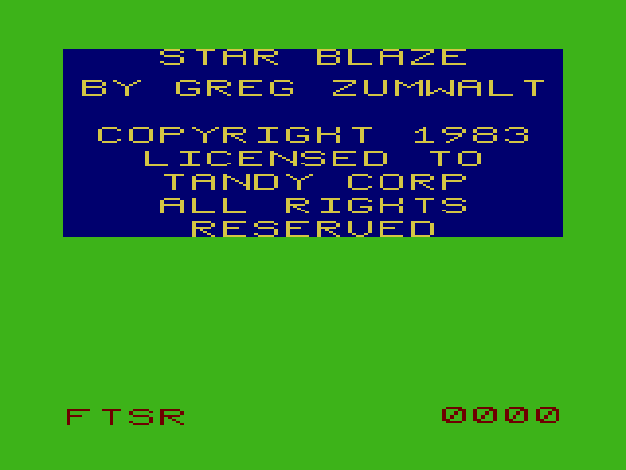
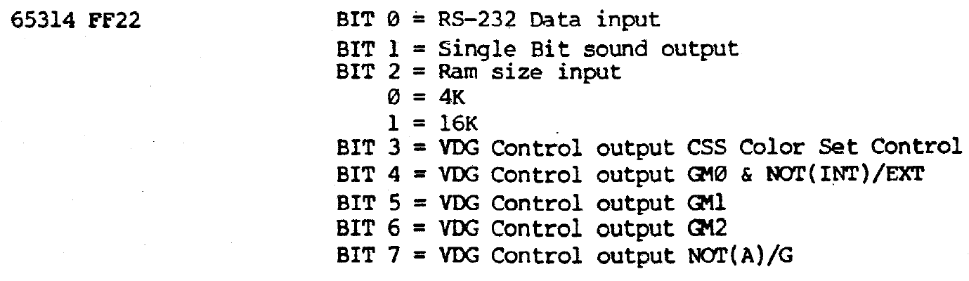
We loaded all this data into RAM, but what actually is this data? Let's take a look at how it looks after we've used it for the four characters 'F', 'T', 'S', 'R', used as labels on the gauges in the bottom left of the screen.

When we were looping through our data we noticed that we were spacing it 32-bytes apart, so lets look at it in 32-byte rows:

1D00: 3F FC 0F FC 0F F0 3F F0 00 .. 
1D20: 30 00 00 C0 30 0C 30 0C 00 .. 
1D40: 30 00 00 C0 30 00 30 0C 00 .. 
1D60: 3F C0 00 C0 0F F0 3F F0 00 .. 
1D80: 30 00 00 C0 00 0C 33 00 00 .. 
1DA0: 30 00 00 C0 00 0C 30 C0 00 .. 
1DC0: 30 00 00 C0 30 0C 30 30 00 .. 
1DE0: 30 00 00 C0 0F F0 30 0C 00 .. 

There are only 9 distinct values used ($00, 0C, 0F, 30, 33, 3F, C0, F0 and FC), but more importantly, if you ignore the zeros you get some interesting patterns:

1D00: 3F FC  F FC  F F  3F F     .. 
1D20: 3        C  3   C 3   C    .. 
1D40: 3        C  3     3   C    .. 
1D60: 3F C     C   F F  3F F     .. 
1D80: 3        C      C 33       .. 
1DA0: 3        C      C 3  C     .. 
1DC0: 3        C  3   C 3  3     .. 
1DE0: 3        C   F F  3   C    .. 

Hel-lo! The shapes of an F, T, S and R are clearly distinct.

It's even more obvious once we convert them to binary. Here's the F by itself:

1D00: 0011 1111 1111 1100 ..
1D20: 0011 0000 0000 0000 ..
1D40: 0011 0000 0000 0000 ..
1D60: 0011 1111 1100 0000 ..
1D80: 0011 0000 0000 0000 ..
1DA0: 0011 0000 0000 0000 ..
1DC0: 0011 0000 0000 0000 ..
1DE0: 0011 0000 0000 0000 ..

and without the zeroes to make it really obvious:

1D00:   11 1111 1111 11   ..
1D20:   11                ..
1D40:   11                ..
1D60:   11 1111 11        ..
1D80:   11                ..
1DA0:   11                ..
1DC0:   11                ..
1DE0:   11                ..

I remember being blown away by this when I first saw it done years ago. We're literally drawing in 1's and 0's. And we can at last name our $Y_2$ variable.

$$ Y_2 = \mathtt{glyph\_data\_address} $$

This is a very rarely used technique in modern times. It's about the most primitive possible way of embedding graphics into a program. It only really works if you want your shapes to be not only monochromatic, but entirely toneless i.e. only 2 colors.

Initialize HUD gauges ($C09D—C0AD)

C09D: 10 8E C0 A9  LDY #$C0A9  Set Y = $C0A9
C0A1: 8E 1D 00     LDX #$1D00  Set X = $1D00
C0A4: BD D8 6C     JSR $D86C   Jump with return
C0A7: 20 05        BRA $C0AE   Jump

We're setting a couple of address registers before we jump to a subroutine. Without any certainty, we can take a guess at what's going to happen based on the data pointed to by these registers.

The X address refers to an arbitrary area in RAM that we haven't previously touched; the "nice round number" of the address suggests that we might be loading some variables or data into here.

The Y register refers to some instructions in the cartridge ROM which start just a few bytes ahead at $C0A9:

C0A9: 46           RORA
C0AA: 54           LSRB
C0AB: 53           COMB
C0AC: 52           ?????
COAD: 04 C6        LSR $C6

The disassembler has interpreted these bytes as 8-bit instructions that don't make a lot of sense, and one instruction at $C0AC that can't be decoded at all (the 6809 has no valid operation for the instruction 52). Whenever we see this, we can often assume that these are not instructions for the CPU to process, but simply data. Most disassemblers are not sophisticated enough to tell the difference and, to be fair, it's sometimes next to impossible to know the difference until the program is executing.

Look at what happens if we try interpreting these bytes as ASCII characters instead:

C0A9: 46           'F'
C0AA: 54           'T'
C0AB: 53           'S'
C0AC: 52           'R'
COAD: 04           EOT (end of transmission)

Now this looks promising, and rather familiar, as our in-game gauges use exactly these abbreviations:

F T S R Gauges

The byte 04 at $C0AD is not a renderable ASCII character, but its definition as an "end of transmission" marker suggests that it may signal the point at which we should stop interpreting bytes as text.

With these clues it would be fair to guess that we're going to be rendering the gauge labels to the screen.

Paint the sky blue ($C090—C09C)

C090: 8E 06 00     LDX #$0600   Set X = $0600 (start of video memory)
C093: CC AA AA     LDD #$AAAA   Set D = $AAAA (blue)
C096: ED 81        STD ,X++     Store
C098: 8C 12 00     CMPX #$1200  
C09B: 26 F9        BNE $0096    Loop until $1200

Here we set all of the memory from $0600 to $1200 to the value $AA. As this constitutes 3K of data, or exactly half of the total video memory, we can deduce that the top half of the screen is being painted a certain color.

Now would be a good time to see what values we need to set in memory to paint on the screen, so we turn to page 21 of the MC6847 VDG technical specifications.

Graphics data formats

Each byte of data in video memory can be visualized like this:

Color Graphics Data Format

D0 to D7 represent the individual bits in each byte. The byte is divided into four; each pixel on screen is represented by 2 bits. We'll look at what values those 2 bits should be shortly.

Remember that we've set the display mode to "color graphics"; in contrast, look at the data format for each byte if the display mode were set to "resolution graphics":

Resolution Graphics Data Format

Again, D0 to D7 represent the individual bits, but here the byte is divided into eight; each pixel is represented by only one bit.

Color selection and chroma/luma

A mildly interesting note on terminology from the diagrams above: "chroma" refers to data that carries information about color; "luma" refers to achromatic, or "black-and-white", data.

In "resolution graphics" mode we aren't working with colors, so our data can be defined as purely luma. On a more capable computer with enough RAM for 8 bits per pixel, such luma might use a value of 0 for white, 255 for black, and any number in between for the various levels of grey between the two. On the CoCo, with only one bit per pixel, we can really only specify a 0 for "pixel off" and a 1 for "pixel on". In practice a 0 results in a green and a 1 results in a muddier green.

In "color graphics" mode we have 2 bits per pixel. The pixel color can be determined according to this table:

Color selection on the MC6847

Look at the CSS column first. This determines which of two system palettes we can use. Since we haven't set this it will be initialized to zero, so we get the default green/yellow/red/blue palette.

The D7 and D6 columns (not to be confused with the individual data bits discussed in the previous section) represent the 2 bits of data for each pixel. To take our specific code under consideration, we've set all of our bytes to $AA, which in binary is 1010 1010. This means that each pixel has the first bit set to 1 and the second bit set to 0. This corresponds to the fourth line of the table, or Blue.

We have painted the sky blue.

What's a pixel in this case?

A final point: our pixels may not be quite what you think of today, where LCD screens have fixed physical pixels. On a raster TV, each pixel is drawn as an electron gun quickly fires horizontal lines across the screen. A pixel's width is therefore determined by the amount of time it takes to switch from one element of data to the next, while its height is measured in the number of horizontal scanlines it uses.

At a resolution of 128 x 192, each pixel is 2 VDG half-clock cycles wide (probably a few hundred nanoseconds) and one scanline high. Each pixel appears to be relatively chunky and wide, like this:

Pixel shape for CG6

Other video modes, like CG2 at 128 x 64 (2 half-clock cycles x 3 scanlines), are even chunkier, but do have a somewhat squarer shape e.g.

Pixel shape for CG2

Initialize unknown variables $2029—$202A ($C08C—C08F)

C08C: 0F 29        CLR $29      Set $2029 = 0
C08E: 0F 2A        CLR $2A      Set $202A = 0

Here's our first instance of direct addressing; since we already set the offset to 0x2000, the CLR $39 actually means CLR$2039. I presume one or two variables will be stored here, though we don't yet know what they are.

Initialize frame count ($C087—C08B)

C087: CC C0 00     LDD #$C000   Set D = 49152 ($C000)
C08A: DD 67        STD $67      Store to $2067

The 2-byte variable at $2067 reveals itself once we observe it with the game in motion. Each time a VSYNC occurs, i.e. for each frame, it increments by one. Therefore, it seems reasonable to call this variable frame_count.

It starts at $C000, but once it reaches $DFFF (after 8,191 frames) it resets back to $C000 and starts again.

Initialize unknown variable ($C082—C084)

C082: CC 0A 8C     LDD #$0A8C   Set D = 2700 ($0A8C)
C085: DD 55        STD $55      Store to $2055

I can't find anywhere that reads data from $2055; I don't know what the point of the variable at that location is.

Set skill-based variable 2 ($C06F—C081)

C06F: B6 27 00     LDA $2700    Set A = skill_level
C072: 4A           DECA         skill_level - 1
C073: 26 05        BNE $007A    Branch to $007A if skill_level - 1 > 0
C075: CC 00 80     LDD #$0080   Set D = 128
C078: 20 06        BRA $0080    Branch to $0080
C07A: C6 10        LDB #$10     Set B = 16
C07C: 3D           MUL          (skill_level - 1) x 16
C07D: C3 00 80     ADDD #$0080  + 128
C080: DD 65        STD $65      Store result to $2065

This is doing a very similar thing to the previous calculation using the skill level, but with a multiplier of 16 instead of 80.

$$ \begin{array}{l@{\,}l} x & = ((\mathtt{skill\_level} - 1)\times16) + 128 \end{array} $$

This time there's some branching which will avoid extra calculations when the skill_level is 1; the resulting zero in the formula means we can set the result directly to 128. This strikes me as an unnecessary optimisation to be honest; for those 7 extra bytes of program space, we save a few CPU cycles in a non-critical function, but only when the user is playing on the easiest level. It would not make any noticeable difference to the player.

Again we don't know exactly what this variable is used for yet, but the possible values are:

skill_level value
1 128 ($80)
2 144 ($90)
3 160 ($A0)
4 176 ($B0)
5 192 ($C0)
6 208 ($D0)
7 224 ($E0)
8 240 ($F0)

This time the result is never more than 8 bits, so there's no extra instructions needed to deal with 16-bit results.

Set skill-based variable 1 ($C04B—C06E)

C04B: 0F 39        CLR $39      Set 0x2039 to 0

This perhaps signifies a single byte variable, but it doesn't seem to be used anytime soon. We'll have to come back to it later.

C04D: B6 27 00     LDA $2700    Set A = skill_level
C050: 4A           DECA         skill_level - 1
C051: C6 50        LDB #$50     Set B = 80
C053: 3D           MUL          (skill_level - 1) x 80
C054: C3 00 80     ADDD #$0080  + 128
C057: DD 45        STD $45      Store result to 0x2045
C059: DD 47        STD $47      Store result to 0x2047

Earlier we identified $2700 as the skill_level variable, which has a range of 1 to 8. We use that value now to perform a calculation:

$$ \begin{array}{l@{\,}l} x & = ((\mathtt{skill\_level} - 1)\times80) + 128 \\ \end{array} $$

We don't know what this number signifies yet, but for skill ranges 1 to 8 it would be set to:

  • skill level 1 = 128 ($80)
  • skill level 2 = 208 ($D0)
  • skill level 3 = 288 ($120)
  • skill level 4 = 368 ($170)
  • skill level 5 = 448 ($1C0)
  • skill level 6 = 528 ($210)
  • skill level 7 = 608 ($260)
  • skill level 8 = 688 ($2B0)

For the following code, let's assume that the skill level is set to 8, so the result is $02B0.

C05B: 96 46        LDA $46      Set A = 176 ($B0)
C05D: C6 55        LDB #$55     Set B = 85
C05F: 3D           MUL          176 x 85 = 14960 ($3A70)

I'm glad this processor has its own multiply instruction. It takes 11 CPU cycles, but it could be worse; apparently on the Intel 8086/8088 these instructions took up to 200 cycles.

Anyhow, we've multiplied only the lower byte of the 2-byte value we calculated and stored at $2045. Why?

Performing arithmetic on just one part of a multi-byte value might look strange at first, but we'll probably end up multiplying the other byte later and then adding the two together. On an 8-bit processor, this is the only way to multiply two numbers that might give a result of 16 (or more) bits.

In short, we're probably just trying to do this:

$$ \begin{array}{l@{\,}l} y & = 688\times85 = 58480 \end{array} $$
C060: 34 06        PSHS ,B,A    Push 3A70 to the stack

Now we push the result of that lower-byte multiplication to the stack. We saw earlier that the stack could be used to temporarily store data; this is the first time we're actually doing so, in this case on the number $3A70.

Assuming we're still at the top of the stack at 0x3FFF, this 2-byte number will be saved at location 0x3FFD.

C062: 6F E2        CLR ,-S      Store 0x3FFC = 0, Set S = 3FFC
C064: 96 45        LDA $45      Set A = 2
C066: C6 55        LDB #$55     Set B = 85
C068: 3D           MUL          2 x 85 = 170 (0xAA)

Sure enough, we've now performed the multiplication on just the upper byte of the value we generated. I would now expect that we add these two together to get E470.

$$ \begin{array}{r@{\,}r} & \mathtt{3A70} \\ + & \mathtt{AA00} \\ \hline & \mathtt{E470} \\ \end{array} $$

But in 0x0062, why did we decrement the stack one extra byte, and clear that value?

C069: E3 E1        ADDD ,S++    Set D = 3A + AA = 00E4 (228), S = 3FFE 
C06B: 32 61        LEAS +$01,S  Set S = 3FFF (top of stack)
C06D: DD 49        STD $49      Store 0x2049 = 00E4

We haven't quite done what I expected. We are doing an addition, but by

  1. pushing the stack down an extra byte and
  2. leaving the D register containing only the upper-byte multiplication (i.e. 00AA)

we actually end up ignoring the lower byte entirely.

$$ \begin{array}{r@{\,}r} & \mathtt{003A} \\ + & \mathtt{00AA} \\ \hline & \mathtt{00E4} \\ \end{array} $$

It's hard to say why we do that as we don't yet know what this variable is used for. But if we just ignore the lower byte and assume it's zero, the value may be accurate enough for us i.e.

$$ \mathtt{E400}\approx\mathtt{E470} \\ 58368\approx58480 $$

With a skill level of between 1 and 8, all possible values are shown below:

skill value value + lower-byte value at $2049
1 10752 ($2A00) 10880 ($2A80) 42 ($002A)
2 17664 ($4500) 17680 ($4510) 69 ($0045)
3 24320 ($5F00) 24480 ($5FA0) 95 ($005F)
4 31232 ($7A00) 31280 ($7A30) 122 ($007A)
5 37888 ($9400) 38080 ($94C0) 148 ($0094)
6 44800 ($AF00) 44880 ($AF50) 175 ($00AF)
7 51456 ($C900) 51680 ($C9E0) 201 ($00C9)
8 58368 ($E400) 58480 ($E470) 228 ($00E4)

Discarding the lower byte seems pointless...

In this particular case ignoring the lower byte doesn't seem all that useful, but it certainly would be if we were multiplying larger numbers. For example:

$$ \begin{array}{r@{\,}r} & \mathtt{FFB0} \\ \times & \mathtt{0055} \\ \hline & \mathtt{54E570} \\ \end{array} $$

Now we have a 24-bit number that we have to manage. This is much more awkward than a 16-bit number, because we don't even have any registers on the CPU capable of storing the whole number at once. And again, if we just pretend that the lower byte doesn't matter and assume it's zero, the end result is not that much different and much easier to manage. e.g.

$$ \mathtt{54E500}\approx\mathtt{54E570} \\ 5,563,648\approx5,563,760 $$

...but this doesn't make sense

Two things still don't make sense to me:

  1. All possible values are still 16-bit; we would only start to exceed that if the skill_level went to 10 or higher. As-is, the value at $2049 will always be $00.
  2. I can't figure out is why we did a PSHS ,B,A and not just a PSHS ,A. The B register, containing the ignored lower byte in 3FFE, was never touched, so why put it in the stack at all? Not pushing the B register would also have avoided the issue an extra instruction to return to the top of the stack, i.e. the instruction LEAS +$01,S would not have been required.

Kill any lingering sound ($C043—C04A)

C02B: B6 FF 20     LDA $FF20    Load 0xFF20
C02E: 84 03        ANDA #$03    Zero bits 2,3,4,5,6,7
C030: B7 FF 20     STA $FF20    Store

Here we AND the value at 0xFF20 against the bitmask 0000 0011, which sets all of the bits of the 6-bit D/A to 0.

CoCo memory map 0xFF20

What's the "6-bit D/A"? The "D/A" stands for "digital-to-analog converter". At a technical level, this converts the six-bit input (i.e. a number between 0 and 63) and converts it to a voltage (in this case, between 0.25 volts and 4.75 volts). It appears to be a linear conversion; the approximate voltage can be determined by the formula

$$ V = (n\times0.0715) + 0.25 $$

Thus a level of 0 will result in a voltage output of 0.25 volts:

$$ V = (0\times0.0715) + 0.25 = 0.25 $$

And the "full volume" level of 63 results in a voltage output of around 4.75 volts:

$$ V = (63\times0.0715) + 0.25 \approx 4.75 $$

Not that the specific voltages are important for what we're doing... but what is this analog output used for?

Cassette output

Though we always played Starblaze from a cartridge, most of our games and other programs were saved on standard audio cassette tapes. I never really knew how that worked; how do you store a program as sound?

Once I knew (vaguely) the difference between analogue and digital I was even more confused: how can we store digital data, which is ultimately just discrete ones-and-zeroes, on an analogue medium, which stores sound in a very non-discrete manner i.e. with an effectively infinite resolution?

It turns out to be fairly straightforward and it's been explained on page 32 of the TRS-80 Color Computer Technical Reference Manual for at least the last thirty five years:

Digital storage on cassette tape

In brief:

  1. If you want to save a 0 to tape, generate one cycle of a 1200Hz sine wave.
  2. If you want to save a 1 to tape, generate one cycle of a 2400Hz sine wave.

I am not enough of an electrical engineer to know exactly how those analog signals are generated, nor how they are reconverted to digital during a load, but to know the format of the storage is enough for me.

Interestingly, since you literally could hear the program being loaded from the cassette tape (somewhat akin to this recording of Apple I BASIC (source)), it's actually relatively easy for modern computers to convert the audio files of programs being loaded by cassette back into the source data. I find it enjoyably perverse that the medium in which that analogue audio is stored is itself digital.

Sound output

The other common use of digital-to-analogue conversion, which unlike the previous example still lives to this day, is to play actual sound. 6-bit audio is not very high quality at all, though I've always had a soft spot for the effectiveness of the CoCo sound effects. In Starblaze's case, I love the klaxon alarm that erupts when aliens appear, especially when, in the absolute stillness of a clear sector, it crashes in upon you as you're idly perusing the map. Such panic!

You could also get some ugly speech synthesis; the "WE GOTCHA!" of MegaBug is another one that's hard to forget.

So...

Given all of that, and given that we're not doing anything with the cassette tape, my suspicion is that these lines of assembly are designed to kill any lingering sound effects. After a hard reset this is likely to already be zero, but perhaps after a soft reset this is not always the case.

Set IRQ delegate ($C03D—C042)

C03D: 8E C2 7C     LDX #$C27C  
C028: BF 01 0D     STX $010D   Set 0x010D to C2 7C (pointer to 0xC27C)

We're writing some bytes to 0x010D, so first things first: what's at that location?

CoCo memory map 0x010C to 0x010E

This lies amidst a larger collection of "interrupt vectors", which basically just tells us what to do when the CPU is interrupted by an external event. This is the IRQ interrupt vector, which means that a hardware event - such as a VSYNC - will cause execution to jump to 0x010C.

Once we're at 0x010C, we only have 3 bytes before the next piece of (unrelated) system code; we don't want to let the CPU keep running into that code, so for practical purposes the only thing we can do in such a limited space is jump to another function. In fact this is so common that we assume that the op-code byte at 0x010C is already set to JMP (7E), and don't bother setting it. Instead we just set the address for the JMP at 0x010D.

In short, whenever a hardware interrupt occurs, execution will jump to 0xC27C.

A note on pointers

Here we're loading an address in the X register, but for the first time, rather than saving the value at that location we're actually writing the address itself to 0x010D. This is basically what a pointer in any higher-level language is; not a value, but the address pointing to that value.

Typically, when learning a language like C, we first encounter pointers to simple variables. In this case, however, 0xC27C is not a variable, but executable code i.e. the starting point of another function.

In other words, in our 6 bytes of code we've written a function pointer (albeit one at a fixed location).

It's gnarly that pointers (let alone function pointers) can be difficult for learner programmers starting in a high-level language, but in assembly both the concept and the implementation are very straightforward to understand.

Enable VSYNC interrupts ($C032—C039)

C020: B6 FF 03     LDA $FF03   Load data from 0xFF03
C023: 8A 01        ORA #$01    Set bit 0 (OR on 0000 0001)
C025: B7 FF 03     STA $FF03   Save back to RAM
C03A: B6 FF 02     LDA $FF02   Touch 0xFF02 to clear flags

Here we're writing a mask to the I/O system via the SAM again, just as we did before to set the VDG mode. This time it corresponds to the I/O0 (Slow) flags.

MC6883 I/O memory mapping

Again, the detailed memory map comes to the rescue:

CoCo Memory Map at 0xFF03

So we're enabling "IRQ to CPU" for the field sync. A field sync is the same as a vertical sync (VSYNC); this is the small pause that occurs 60 times a second, once the electron beam has drawn the entire screen (all 525 horizontal lines) and is returning to the upper-left corner. An interrupt signal that it sends at this time is most usefully read as a message from the video controller saying, "Hey! I've drawn the whole screen but I haven't started on the next one yet; if there are any changes you want to make for the next screen, now might be a good time to do it."

It might be useful to see what happens to the game if we don't allow the CPU to be notified of the VSYNC. To get a better idea of what this does I tried setting the byte at 0x36 from 01 to 00, which causes the code to do nothing and keeps the IRQ to CPU disabled. What happened was this:

What happens with IRQ to CPU disabled for vertical sync

We get the basics of the HUD displayed, but nothing else. The game appears to be otherwise locked on this screen. I would guess this means that the program is actually waiting for the VSYNC signal before proceeding. It likely does this because writing to the video RAM at the same time that it's being rendered to screen is not usually a great idea (you might end up drawing half of the previous state and half of the new state).

What's that got to do with 0xFF02?

The final instruction in this snippet is LDA $FF02, which appears to make no sense because we don't subsequently do anything with the stored value.

The only information I've been able to find so far - though it's probably formally documented somewhere; is in an online esoteric discussion of the VSYNC interrupt:

"As to your question about reading $FF00 or $FF02, that clears the interrupt flag of the respective byte $FF01 or $FF03."

Fair enough. Having just enabled the VSYNC interrupt, we want to ensure that the interrupt flag (on bit 7 of 0xFF03) is cleared. In MESS I don't actually see the data on 0xFF03 change, nor does skipping this instruction seem to affect the game.

Clear memory for variables ($C028—C031)

C01C: 8E 20 00     LDX #$2000   Set X to address 0x2000
C02B: 6F 80        CLR ,X+      Set memory at X to 0
C02D: 8C 26 F9     CMPX #$26F9  Check if we've reached 0x26F9
C01E: 26 F9        BNE $002B    Keep going if not

This zeroes all the memory between 0x2000 and 0x26F9, a total of 1,785 bytes. Perhaps this is where we'll be storing all of our variables and other data?

Not that it's going to make much difference, but I wonder why we don't set 2 bytes at a time like we did when clearing the screen?

i.e.

LDD #$0000   Load D with 0000
STD ,X++     Store 0000 to memory

instead of CLR ,X+ Clear to memory (i.e. store 00)

Possibly because we're dealing with an odd number of bytes here, so if we set two at a time we need to add another instruction at the end to set just one.

Or maybe the routine when clearing the screen was a copy-and-paste from elsewhere, hence just someone else's coding style.

Clear the screen ($C025—C027)

C025: BD D7 DC     JSR $17DC   Jump

The subroutine at $17DC looks like this:

D7DC: 8E 06 00     LDX #$0600
D7DF: CC 00 00     LDD #$0000
D7E2: ED 81        STD ,X++ 
D7E4: 8C 1E 00     CMPX #$1E00
D7E7: 26 F9        BNE $17E2
D7E9: 39           RTS

Huh. So this basically starts at address $0600 - which we established was the start of video memory - and zeroes out all the bytes until $1E00. Funny, I always thought that zeroing out memory could be done in a single bulk operation somehow, but nope, we have to loop 3,072 times, zeroing out 2 bytes at a time.

It's no coincidence that we're zeroing out exactly 6K of RAM. We previously established that the video RAM would start at $0600, and that the COLOR GRAPHICS SIX mode would use 6K of RAM.

In other words, we've turned the whole screen green.

Why is my screen not completely green?

Interestingly, even after doing this, if we pause execution and look at the screen there are some random artifacts visible:

Random artifacts after screen clear

Unlike modern LCD monitors, CRT televisions and monitors have an electron gun that fires horizontal beams at the screen, moving back and forth from top-to-bottom. The artifacts that we see are only at the bottom of the screen, which suggests they're remnants from the previous state of the video RAM, from before the memory was cleared. They're still visible simply because the electron gun has not quite reached those scanlines yet. Give the screen a few milliseconds to refresh and it will disappear.

Initialize stack ($C021—C024)

C021: 10 CE 3F FF  LDS #$3FFF  Set stack pointer to 0x3FFF

This instruction sets the memory location for our stack to 0x3FFF. Choosing this particular address is somewhat arbitrary; it just needs to be somewhere that won't be used by anything else.

What is the stack?

The stack can be used for a couple of different things.

Call stack for jumps and returns

If we peek ahead at the next section we'll see that the next command is a JSR (Jump to Subroutine), which will cause execution to jump immediately to a given memory address. It's important, however, that when we want to return from that address, we know where to go back to. The stack will automatically do this for us, and this feature is known as a call stack. For example:

  • following the JSR (Jump To Subroutine) command, the value 0028 will be automatically stored at 0x3FFD, and the stack register S will point to 0x3FFD.
  • following the next RET (Return) command, execution will return to $0028 and the stack register S will point to 0x3FFF again.

Temporary data storage

Notice that the stack grows downwards, so 0x3FFF points to the top of the stack, and anything added to the stack is added at memory addresses below that.

New Game entry point ($C01F—C020)

C01F: 1A 50        ORCC #$50  Disable hardware interrupts

This is identical to $0000, which disabled all hardware interrupts (i.e. disabled all keyboard/joystick inputs). Nothing new there, but $0000 has just been run; the more interesting question is, why are we repeating it?

To me it suggests that this is a subroutine entry point which we'll jump back to later, from a point at which hardware interrupts are probably not disabled. If we search the code for $001f we see that this is true:

C3AB: 16 F6 E3     LBRA $001F   Branch to $001F

By running the game in the debugger, we can see that $001F is executed when:

  1. We first turn on or reset the machine (via execution from $0000)
  2. We start a new game by selecting a skill level from the start screen (via branching from $0939)

Unknown ($C016—C01E)

C016: CC FF FF     LDD #$FFFF  Set D (A and B) with 1111 1111
C019: FD 26 FA     STD $26FA   Store 1111 1111 to 26FA, 26FB
C01C: FD 26 FC     STD $26FC   Store 1111 1111 to 26FC, 26FD

We're setting all the bytes from 0x26FA to 0x26FD to FF (i.e. all 1's). I don't yet know why.

Initialize video ($C013—C015)

C00D: BD D7 B2   JSR $D7B2   Jump to initialize_video()

This first part of this subroutine, which I've named initialize_video() because I know that we're setting up the video display, is shown below.

D7B2: 8E FF C6   LDX #$FFC6   Set X to address for SAM VDG display offset
D7B5: 86 03      LDA #$03     Set A to 3 (binary 000 0011)
D7B7: C6 07      LDB #$07     Set B to 7
D7B9: 8D 12      BSR $D7CD    Call write_to_SAM_register()

"Hang on a minute," you say. "What's this 'SAM'? What's this 'VDG'? What are we doing here?". Fair questions, which require a diversion into how video works for the CoCo.

How video works on the CoCo

The component responsible for rendering video is the Motorola MC6847 Video Display Generator (VDG).

MC6847 - the chip

While modern video cards have their own on-board memory, the VDG reads directly from the same RAM used by the CPU. First you initialize the chip with a display mode and the address at which video data will be stored in RAM. It then sequentially reads all of the screen data from the RAM (between 512 and 6,144 bytes, depending on the display mode set during initialization) and sends that to the monitor. For an NTSC output (i.e. your average TV screen), it reads and sends the data in sync with the rasterization process i.e. 60 times a second.

What is the data in video RAM, and how does that translate to what's shown on-screen? The VDG provides a resolution of 256 x 192, for a total of 49,152 pixels. A modern-day computer could easily spare 3 bytes (24-bit, "true color") per pixel, for a total requirement of 144K. Your average CoCo might only have 16K of RAM in total, so that's out of the question; at maximum resolution, we can really only afford 1 bit per pixel, for a maximum requirement of 6,144 bytes (6K) of RAM.

Of course, if we want any color (and this is the "Color Computer") we have to spare at least a couple of bits per pixel. To accomodate our limited resources, the VDG has 14 modes of varying colors and resolutions, outlined below:

Alphanumeric and "semi-graphics" modes

These aren't of much interest to us as they mostly display text and very crude graphical blocks.

  • ALPHANUMERIC INTERNAL - 32 x 16 characters, 2-color, each byte is an ASCII character. Uses 0.5K RAM.
  • ALPHANUMERIC EXTERNAL - 32 x 16 characters, 2-color, each byte is a custom character. Uses 0.5K RAM.
  • SEMIGRAPHICS 4 - 64 x 32, 8-color. Uses 0.5K RAM.
  • SEMIGRAPHICS 6 - 64 x 48, 4-color. Uses 0.5K RAM.

(There are also SEMIGRAPHICS 8, 12 and 24, not in the VDG manual. I couldn't actually recreate these modes in the emulator and I'm not sure how capable the CoCo was of actually using it).

Semi-graphic and alphanumerics (source)

Resolution modes

These aren't of much interest for games either as you only get 2 colors. I can't think of any programs that actually use it, though looking at the manuals it may have been the only way to get black and white (or rather, "buff") together on-screen.

  • RESOLUTION GRAPHICS 1 - 128 x 64, 2-color. Max 1K RAM.
  • RESOLUTION GRAPHICS 2 - 128 x 96, 2-color. Max 1.5K RAM.
  • RESOLUTION GRAPHICS 3 - 128 x 192, 2-color. Max 3K RAM.
  • RESOLUTION GRAPHICS 6 - 256 x 192, 2-color. Max 6K RAM.

Color modes

Much more interesting as you get 4 vibrant colors to play with.

  • COLOR GRAPHICS 1 - 64 x 64, 4-color. Max 1K RAM.
  • COLOR GRAPHICS 2 - 128 x 64, 4-color. Max 2K RAM.
  • COLOR GRAPHICS 3 - 128 x 96, 4-color. Max 3K RAM.
  • COLOR GRAPHICS 6 - 128 x 192, 4-color. Max 6K RAM.

There are two palettes to choose from; the extremely vibrant green/yellow/blue/red:

Beautiful Whirlybird Run

and the somewhat upsetting buff/cyan/magenta/orange. The game I most distinctly remember that really embraced the latter palette was the (aptly named) Pooyan port.

Ugly Pooyan

Most games on cartridge that I remember would have used CG6 i.e. the maximum resolution. I guess the only reason you wouldn't is to support those with only 4K of RAM.

The SAM

What, another chip?

Yes. The MC6883 Synchronous Address Multiplexer (SAM).

As far as I understand, while the main point of the SAM is act as a RAM controller, the sophisticated bit is that it synchronizes the CPU, the RAM and the VDG to work nicely together. Consider that the VDG needs to read up to 6,144 bytes from RAM, 60 times a second. This is fine, except that the CPU also needs frequent (and uncontended) access to RAM. A fight is clearly brewing.

The SAM cleverly steps around this issue by interleaving CPU and VDG accesses within the same machine cycle. It so happens that all CPUs compatible with the SAM only access memory in the latter half of the machine cycle. The VDG is therefore free to access the RAM in the former half of the machine cycle.

MC6883 Interleaved DMA

Initializing the VDG via the SAM

The graphics mode is controllable, by writing data to special areas of memory accessible to the VDG and the SAM.

First we apply a change to the SAM, which has 11 "bits" that the user can set to configure the chip. I use the term bit in quotes because setting these values is not straightforward; we have 22 bytes of specially mapped memory which we can write data to in order to set or clear a SAM "bit".

MC6883 VDG Mode and Display Offset memory mappings

The subroutine at $D7CD, I'll call write_to_SAM_register():

D7CD: 46         RORA        Load the next bit into the carry bit
D7CE: 24 06      BCC $D7D6   Branch if carry bit is a 0
D7D0: 30 01      LEAX +$01,X Move to the "set bit" memory location
D7D2: A7 80      STA ,X+     "Set" the bit, move to next "clear" bit memory location
D7D4: 20 02      BRA $D7D8   Continue
D7D6: A7 81      STA ,X++    "Clear" the bit, move to next "clear" bit memory location
D7D8: 5A         DECB        B - 1
D7D9: 26 F2      BNE $D7CD   Loop to top while B > 0
D7DB: 39         RTS         Return

As I discovered later, this piece of code is the idiomatic way to set these bits on the SAM, and is actually listed almost exactly as above on page 16 of the MC6883 technical specs.

VDG Address Offset

The addresses 0xFFC6 - 0xFFD3 are mapped to the VDG Address Offset, which indicates the starting address in RAM for video data. It's set in a kinda weird way; individual bits are set by writing to particular bytes of mapped memory:

  • Set any data on 0xFFC6 = clear bit 0
  • Set any data on 0xFFC7 = set bit 0
  • Set any data on 0xFFC8 = clear bit 1
  • Set any data on 0xFFC9 = set bit 1
  • Set any data on 0xFFCA = clear bit 2
  • Set any data on 0xFFCB = set bit 2
  • Set any data on 0xFFCC = clear bit 3
  • Set any data on 0xFFCD = set bit 3
  • Set any data on 0xFFCE = clear bit 4
  • Set any data on 0xFFCF = set bit 4
  • Set any data on 0xFFD0 = clear bit 5
  • Set any data on 0xFFD1 = set bit 5
  • Set any data on 0xFFD2 = clear bit 6
  • Set any data on 0xFFD3 = set bit 6

Now recall again the first part of the subroutine we were looking at:

D7B2: 8E FF C6     LDX #$FFC6   Address for SAM VDG display offset
D7B5: 86 03        LDA #$03     Set A to 3 (binary 000 0011)
D7B7: C6 07        LDB #$07     Set B to 7
D7B9: 8D 12        BSR $17CD    Set SAM, 7 bits with mask 000 0011 at address 0xFFC6

The bold text in the list above indicates the locations that we end up writing to in Starblaze's case, when we set the seven bits of the VDG display offset to 3 (000 00111).

What does the offset of "3" actually mean for the RAM? Well, the offsets are measured in 512 byte chunks. This means that the data begins at 3 x 512 = 1536, or 0x0600. Therefore the data beginning from 0x600 corresponds directly to the output at the upper-left corner of the screen. As it happens this makes sense, as 0x0600 is precisely where the technical documents state that system-reserved RAM ends and the graphics page areas begin.

The amount memory dedicated to video display from that offset depends on which video mode is set, for example:

  • for the lowest resolution modes it will use the next 512 bytes (0x0600---0x0800)
  • for the highest resolution modes it will use the next 6,144 bytes (0x0600---0x1E00)

VDG Modes

We then use the same technique on a different address:

D7BB: 8E FF C0     LDX #$FFC0  Address for SAM VDG mode
D7BE: 86 06        LDA #$06    Set A to 6 (binary 110)
D7C0: C6 03        LDB #$03    Set B to 3
D7C2: 8D 09        BSR $17CD   Set SAM, 3 bits with mask 110

The bits 110 correspond to video mode "CG6" ("G6C" in the earlier diagram), which is definitely the best for games at 128 x 192 with 4 colors.

VDG Modes via I/O mappings

D7C4: B6 FF 22     LDA $FF22  Address for SAM input/output interfaces
D7C7: 8A E0        ORA #$E0   New SAM, 8 bits with mask 1110 0000
D7C9: B7 FF 22     STA $FF22  
D7CC: 39           RTS

We may notice in the previous section that setting 3 bits on the SAM is not actually enough to specify the exact mode that we want; the inputs to the VDG also need to be configured.

SAM and MC6847 inputs for various video modes

Indeed the mask that we set on V0, V1 and V2, 110, could specify CG6 (COLOR GRAPHICS SIX) or RG6 (RESOLUTION GRAPHICS SIX). The only thing separating the two is the bit for GM0, which is configured not on the SAM but on the VDG.

How do we configure the flags on the VDG? It seems that we still do this via the SAM, in this case via the SAM I/O memory mappings in the range FF00 to FF5F:

SAM I/O mappings, FF00 to FF5F

The code specifically sets the byte at FF22. According to the detailed memory map for this address:

Memory map for FF22

a mask of 1110 0000 would set:

  • VDG control output GM1 = 1
  • VDG control output GM2 = 1
  • VDG control output NOT(A)/G = 1

This ensures that the graphics mode is set to 128 x 192, 4-color mode.

Note that when running in MESS, during load the mask is already set to 0000 0100, which indicates 16K of memory vs 4K. We load and then OR the byte from FF22 so that we don't lose existing flags like this.

Fun with video modes

Now that we know how the video mode is set, we can mess up the game in all sorts of interesting ways just by changing a single byte.

If we change 0x17C8 from E0 to F0 we switch from COLOR GRAPHICS SIX to RESOLUTION GRAPHICS SIX:

Video fun with RG6

If we change 0x17C8 from E0 to C0, and 0x17BF from 06 to 04, we get COLOR GRAPHICS THREE:

Video fun with CG3

Finally, if we change 0x17C8 from E0 to 00, we get SEMIGRAPHICS TWELVE:

Video fun with SG12

I'm impressed that the game still runs, and you can almost make out the title.

Initialize skill level ($C00E—C010)

C00E: 86 08        LDA #$08    Set A = 8
C010: B7 27 00     STA $2700   Store 8 in $2700

Via experimentation with the debugger, we can observe that the value at $2700 appears to be set to:

  • 8 when we start/reset the machine and load the start screen
  • 1 when the user starts a game with skill level 1 (easiest)
  • 2 when the user starts a game with skill level 2
  • 3 when the user starts a game with skill level 3
  • 4 when the user starts a game with skill level 4
  • 5 when the user starts a game with skill level 5
  • 6 when the user starts a game with skill level 6
  • 7 when the user starts a game with skill level 7
  • 8 when the user starts a game with skill level 8 (hardest)

It's fairly obvious, then, that the variable at $2700 indicates the skill level. Most likely we initialize it to 8, the hardest skill level, so that the aliens running in "demo mode" on the start screen are plentiful and aggressive.

Unknown ($C006—C00D)

C006: 86 01        LDA #$01
C008: B7 26 FF     STA $26FF   Store 1 in 0x26FF (9983)
C00B: B7 26 FE     STA $26FE   Store 1 in 0x26FE (9982)

We don't know what these values will be used for yet, but the two memory locations $26FE and $26FF are likely to be 1-byte global variables. We can guess this based on two things:

  1. The CoCo memory map tells us that the memory locations don't have any significance for the CoCo; this is part of a block of free memory available to the game.
  2. By searching the program code ahead, we see that these memory locations are referenced frequently from many different code locations.

Set direct address page ($C002—C005)

C002: 86 20        LDA  #$20
C004: 1F 8B        TFR  A,DP   Set to page 32 (offset 0x2000)

This is essentially a technique for saving bytes in the program code. Normally, a memory address (let's say $2010) is specified by the full 16-bit address e.g.

JSR $2010

The direct page (DP) register specifies which memory page to use when using direct addressing mode in all subsequent instructions. In effect this sets a default value for the upper 8 bits of direct-addressed addresses:

i.e. ADDRESS = DP REGISTER + OPERAND (1 byte)

This means that any addresses between $2000 and $20FF can be specified with one byte instead of two e.g.

JSR $10       Jump to $2010

By implication, the 6809 considers a single memory page to be 256 bytes. There are 256 such pages available for addressing. (e.g. 256 pages x 256 bytes = 64KB).

The initial LDA is required because the DP register cannot be set directly, but can be transferred to.

I'm not yet sure why address $2000 (8192) is chosen for the direct page. This makes most sense as an offset from the starting address of the ROM itself, which is exactly 8192 bytes (8K). But if we're talking about RAM, the CoCo makes available the data from 0600 to the top of RAM (3FFF for 16K, 7FFF for 32K). This also overlaps with the graphics pages; I don't understand how these work yet.

Disable hardware interrupts ($C000—C001)

Here's our first line of code:

C000: 1A 50        ORCC #$50   Set condition codes to disable IRQ

We start execution at address $C000.

C000?! Why C000?!

You might expect that when you turn the computer on it'd be sensible to start executing instructions from memory address $0000. The 8080, Intel's second ever 8-bit CPU created in 1974, did actually start reading from $0000. Later microprocessors would start execution at the end of memory; Intel's iconic 8086, the very first x86 processor, starts execution at $FFFF0 while the Motorola 6809, used in the CoCo itself, starts execution at $FFFE.

In that case, why doesn't our code begin at $FFFE? Because our game is not the first piece of code to run when we switch the machine on. We have to remember that our game code is not part of the CoCo itself, but sitting in the circuits of the plastic cartridge that we've pushed into the box, so we shouldn't really expect to be given the honour of being mapped to the prime position of $FFFE. We can see where it's actually addressed by looking at the simplified CoCo memory map:

CoCo Simple Memory Map

Our plastic cartridge is the Program Pak™ Memory, which the map tells us resides at $C000. Hence, our program starts directly at $C000.

Condition Codes

The Motorola 6809 has the following condition codes (source):

Condition codes register for the 6809

The ORCC command will perform a logical OR on the register with a byte, allowing any of these flags to be set manually. In this case the bitmask of 0x50 is:

0101 0000

which corresponds to these two flags:

  • INTERRUPT REQUEST MASK
  • FAST INTERRUPT REQUEST MASK

As far as I understand, the latter is just a higher priority interrupt.

Presumably interrupts are disabled as a safety measure. We're not yet ready to handle any keyboard or joystick button presses the player gives us, so we disabled all inputs until initialization is complete.